Series 2600 System SourceMeters Reference Manual Source-Measure Concepts 8-25
Return to Section 8 topics 2600S-901-01 Rev. A / May 2006
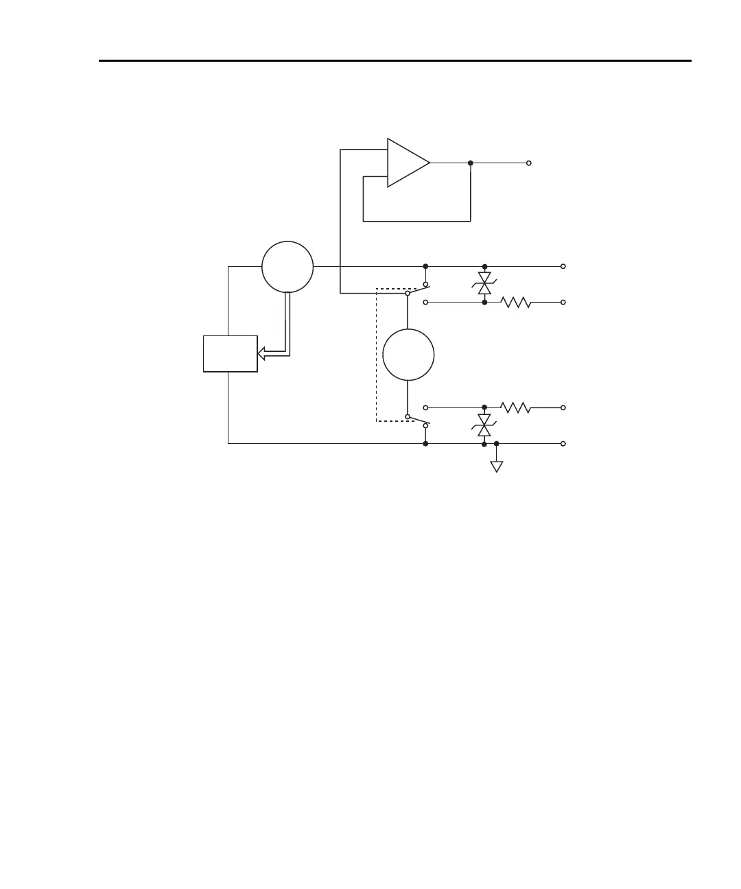
Figure 8-11
Source I conf
Remote
SENSE HI
IN/OUT HI
Remote
IN/OUT LO
I-Source
x1
V-Meter
SENSE LO
Local
Local
GUARD
+
I-Meter
NOTES:
1. This represents a protection circuit that is very
high impedance until the voltage across it exceeds
approximately 3V. Above 3V, the protection turns
on and allows current to flow through it.
2. Approximately 13kW.
1
2
2
1
Feedback
iguration
Source V
When configured to source voltage (V-Source) as shown in Figure 8-12, the
SourceMeter functions as a low-impedance voltage source with current limit
capability and can measure current (I-Meter) or voltage (V-Meter).
Sense circuitry is used to continuously monitor the output voltage and make
adjustments to the V-Source as needed. The V-Meter senses the voltage at the
input/output terminals (2-wire local sense) or at the DUT (4-wire remote sense
using the sense terminals) and compares it to the programmed voltage level. If
the sensed level and the programmed value are not the same, the V-Source is
adjusted accordingly. Remote sense eliminates the effect of voltage drops in the
test leads ensuring that the exact programmed voltage appears at the DUT.
The voltage error feedback to the V-Source is an analog function. The source
error amplifier is used to compensate for IR drop in the test leads.
 Loading...


