21 (37)
Kemppi OY
1.3. Gas guard S003 (optional)
• Gas guard (shielding gas pressure) can be monitored with wire feeder microcontroller. Gas guard switch is closed if
there is enough pressure in the shielding gas line. If pressure is too low, gas guard switch is opened and microcontrol-
ler sends error to system software which prevents or stops the welding
1.4. Door switch S004 (optional)
• Door switch can be attached to the wire feeder. Door switch is monitored with microcontroller and system software
prevents or stops the welding if wire feeder door is open.
1.5. Motor control card A001
• MXP 37 Pipe wire feeder is controlled by microcontroller. Microcontroller has integrated CAN (Control Area Network)
module which makes possible to implement CAN bus between other controllers
• Wire feeder motors are controlled by PWM-circuits N12 and N13. PWM circuits get target values based on set value
from welding panel and measurement made by wire feed motor 1. Motor 1 rotation speed is calculated from motor
tacho-pulses measured by microcontroller. Both motor’s emf (electromagnetic force) are also measured. This makes
it possible to determine motor 1 and 2 speed differences and so on notify if either of the motor wheel spins. Micro-
controller calculates directly both motor currents and motor 2 control is based on same currents in both motors
1.6. Wire feed unit GT04
• There are two identical motor drives for motor 1 and 2. PWM circuit N13 controls motor 1 (the motor near to wire
spool), which has a control feedback loop from tachometer. PWM circuit N12 controls motor 2, which has no feed-
back loop
• Microcontroller software gives warning if motor 1 and 2 sum current is over 3,5A continuously (default) over 20 sec-
onds
• Microcontroller software gives error and interrupt welding if motor 1 current is over 4,5A continuously over 60 sec-
onds or over 6,5A continuously over 30 seconds or over 8A continuously over 20 seconds
• Hardware current limit for both motors are 10A
1.7. Memory card A003
• This card is mounted directly onto the A001 card, and holds all the “set-up” (from power source panel) and the “weld-
ing” parameters for the complete package, this information is transferred between panels and devices, via a CAN bus
network, with KeBus (Kemppi bus) and KeFS (Kemppi file system) protocols
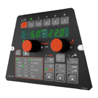
1.8. Panel card P001
• Panel is connected to the A001 card via a ribbon cable.
• Panel is used to select values and parameters and it’s connected to the motor control card A001
 Loading...