1 (37)
Kemppi OY
CONTENTS
FASTMIG X 450 ..................................................................................................................................................................................... 4
TECHNICAL DATA ..................................................................................................................................................................................... 4
1. MAIN CIRCUIT DIAGRAM ........................................................................................................................................................................ 5
1.1. Forced cooling components ........................................................................................................................................................... 5
1.2. Control side devices ....................................................................................................................................................................... 5
1.3. Overheat protection PTCs (Rg101, Rt101, Rg201) .......................................................................................................................... 5
2. MAIN CIRCUIT CARD Z001 ...................................................................................................................................................................... 6
2.1. EMI filtering .................................................................................................................................................................................... 6
2.2. Three phase rectifier V6 ................................................................................................................................................................. 6
2.3. Turn-on transient suppression ....................................................................................................................................................... 6
2.4. Current transformer (T1) ................................................................................................................................................................ 6
2.5. Power stage(IGBT) .......................................................................................................................................................................... 6
2.6. Connectors ..................................................................................................................................................................................... 7
3. DC-LINK CAPACITOR CARD Z002 ............................................................................................................................................................. 8
3.1. Capacitors (C1-C8) and discharge resistors (R1-R4) ....................................................................................................................... 8
3.2. Connectors ..................................................................................................................................................................................... 8
4. SECONDARY RECTIFIER CARD Z003 ........................................................................................................................................................ 9
4.1. Connectors ..................................................................................................................................................................................... 9
5. SECONDARY CUT OFF CARD Z004 ......................................................................................................................................................... 10
5.1. Connectors ................................................................................................................................................................................... 10
6. GATE DRIVER CARD A001 ..................................................................................................................................................................... 11
6.1. Auxiliary power supply ................................................................................................................................................................. 11
6.2. IGBT driver11
6.3. Auxiliary device connection ......................................................................................................................................................... 11
6.4. Voltage monitoring ...................................................................................................................................................................... 11
6.5. Leds ................................................................................................................................................................................... 12
6.6. Connectors ................................................................................................................................................................................... 12
7. PROCESSOR CARD A002 ....................................................................................................................................................................... 14
7.1. Power supply ................................................................................................................................................................................ 14
7.2. Microcontroller ............................................................................................................................................................................ 14
7.3. FPGA (field programmable gate array) ......................................................................................................................................... 14
7.4. Cut-off card connection ............................................................................................................................................................... 15
7.5. Analog (current and secondary voltage measurements) ............................................................................................................. 15
7.6. Machine size jumpers J1, J2 ........................................................................................................................................................ 15
Power source X 450 has a jumper fitted between connector X9:2, 5 ................................................................................................. 15
7.7. Primary current limit .................................................................................................................................................................... 15
7.9. Connectors ................................................................................................................................................................................... 16
8. SYSTEM CARD A003 .............................................................................................................................................................................. 17
8.1. Power supply ................................................................................................................................................................................ 17
8.2. Leds ................................................................................................................................................................................... 17
8.3. Connectors ................................................................................................................................................................................... 17
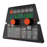
9. SETUP PANEL CARD P001 ..................................................................................................................................................................... 18
9.1. Setup panel card P001 ................................................................................................................................................................. 18
9.2. Connectors ................................................................................................................................................................................... 18
10. OTHER COMPONENTS ........................................................................................................................................................................ 18
 Loading...