EN
2.13 Shielding gas
The MIG shielding gas consists of carbon dioxide, mixed gases and argon. Shielding gas
ow rate is determined by the amount of welding current. The typical ow rate of gas in the
welding steel is 8–15 l /min.
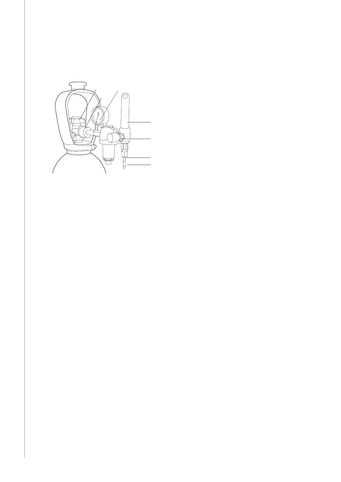
Parts of gas ow regulator
E
B
D
G
A
F
C
A. Gas bottle valve
B. Press regulation screw
C. Connecting nut
D. Hose spindle
E. Jacket nut
F. Gas bottle pressure meter
G. Gas hose pressure meter
The following installation instructions are valid for most gas ow regulator types:
1. Step aside and open the bottle valve (A) for a while to blow out possible impurities.
2. Turn the press regulation screw (B) of the regulator until no spring pressure can be felt.
3. Close the needle valve if there is one in the regulator.
4. Install the regulator onto bottle valve and tighten the connecting nut (C) with a wrench.
5. Install the hose spindle (D) and jacket nut (E) into the gas hose and tighten with a hose
clamp.
6. Connect the hose with the regulator and the other end with the wire feed unit. Tighten
jacket nut.
7. Open the bottle valve slowly. The gas bottle pressure meter (F) shows bottle pressure.
Note! Do not use the whole contents of the bottle. The bottle pressure should be lled
when bottle pressure is 2 bar.
8. Open the needle valve if there is one in the regulator.
9. Turn the regulation screw (B) until the hose pressure meter (G) displays the required ow
(or pressure). When regulating the ow amount, the power source should be switched
on and the "GAS PURGE" -switch pressed simultanously.
Close the bottle valve after welding is nished. If the machine will not be in use for a long
time, unscrew the pressure regulation screw.
NOTE! Always fasten the gas cylinder securely in an upright position on a wall rack intended for the
purpose or on a cylinder cart. Always close the cylinder valve after you have nished welding.
Kempact Pulse 3000, KempactCool 10
8
 Loading...