22
Kemppi Oy
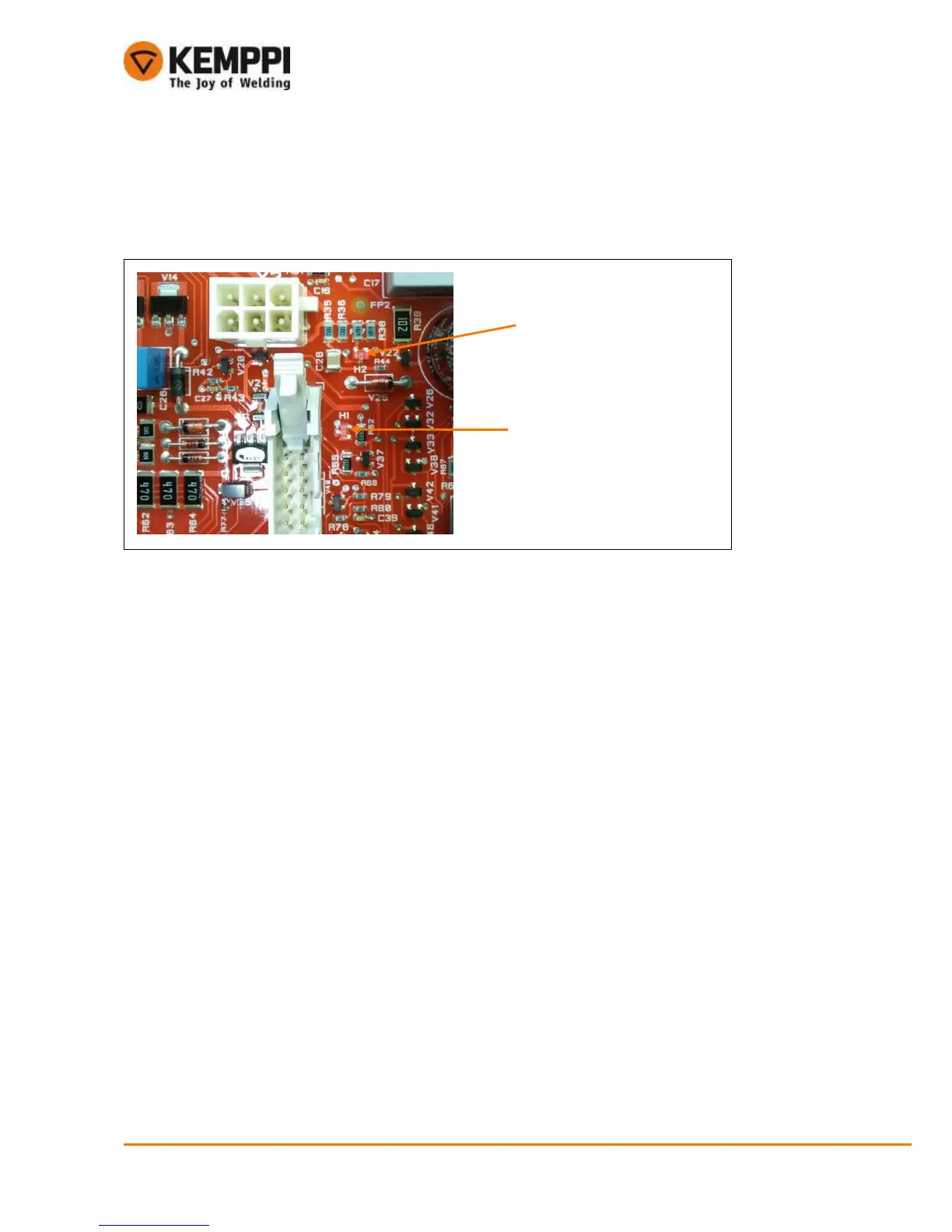
4.2.2. A001 control card
Control card voltages +5VDC and +24VDC can be quickly verified with LEDs on the A001 control card.
Voltages are in secondary side.
4.2.3. Cooling fan
Cooling fan gets the power from +24VDC line. Voltage can be measured on the X13 connector (X13-1
+24VDC and X13-2 GND). Note that the cooling fan has delayed starting.
4.2.4. Low voltage tests
There is no possibility to do low voltage test for this machine.
4.2.5. Safety tests
Safety tests are made normally. Note that PE conductivity test point and chassis ground test point is in
gas valve snap connector.
4.3. Semiconductor installation
It is a must to use torque screwdriver while tightening any power components onto the heat sink.
See following sections for tightening torques.
4.3.1. Rectifier/PFC module and IGBT
MinarcTig Evo 200 has a soldering input rectifier/PFC and IGBT modules and it is not possible to change
them separately. Only reliable way to replace the module(s) is to change the whole Z001 main circuit
card.
 Loading...