126 Keysight InfiniiVision 2000 X-Series Oscilloscopes User's Guide
10 Triggers
You can save trigger setups along with the oscilloscope setup (see Chapter 18,
“Save/Recall (Setups, Screens, Data),” starting on page 229).
Triggers - General
Information
A triggered waveform is one in which the oscilloscope begins tracing (displaying)
the waveform, from the left side of the display to the right, each time a particular
trigger condition is met. This provides stable display of periodic signals such as
sine waves and square waves, as well as nonperiodic signals such as serial data
streams.
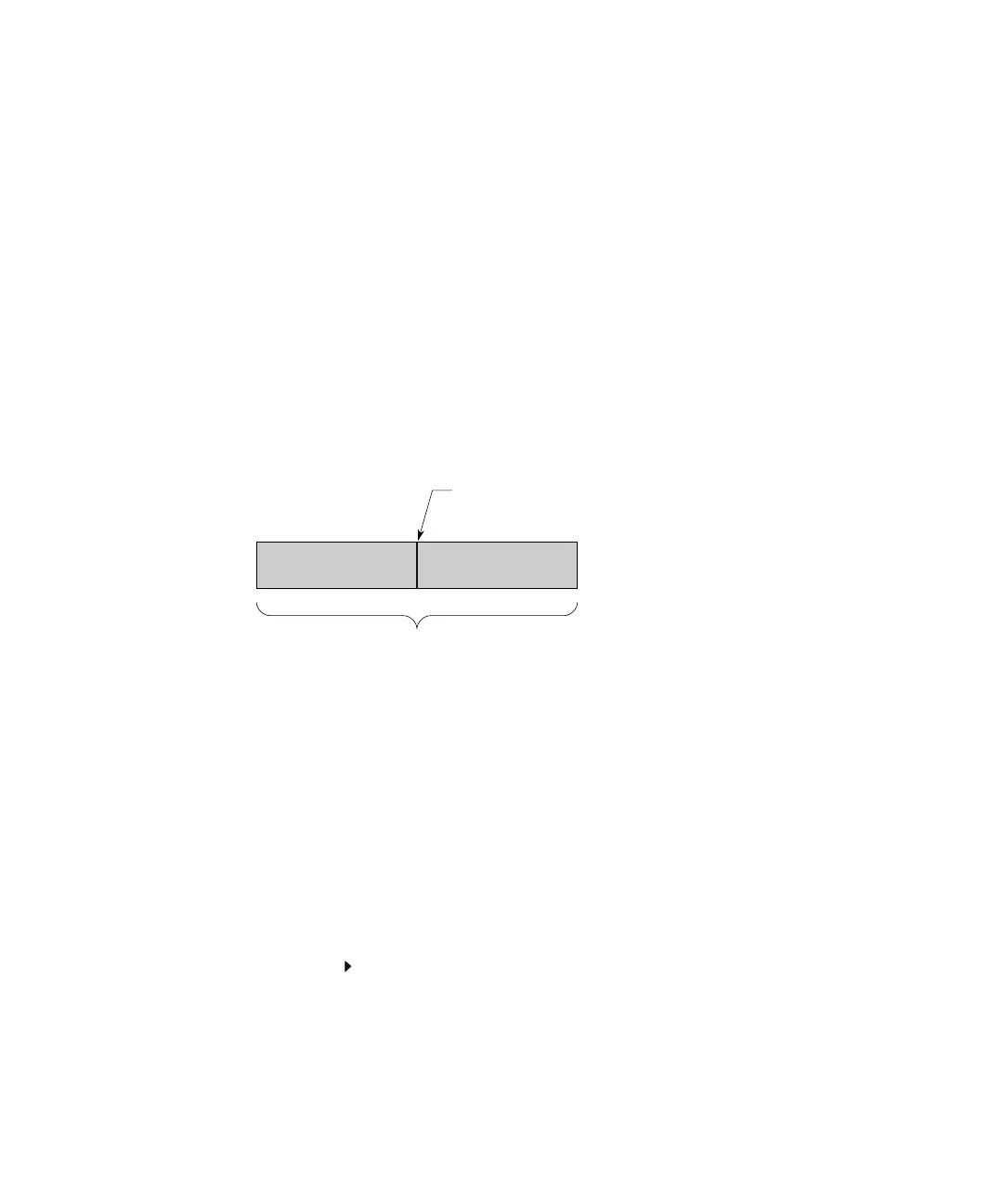
The figure below shows the conceptual representation of acquisition memory. You
can think of the trigger event as dividing acquisition memory into a pre-trigger
and post-trigger buffer. The position of the trigger event in acquisition memory is
defined by the time reference point and the delay (horizontal position) setting (see
“To adjust the horizontal delay (position)" on page 51).
Adjusting the Trigger Level
You can adjust the trigger level for a selected analog channel by turning the
Trigger Level knob.
You can push the Trigger Level knob to set the level to the waveform's 50% value.
If AC coupling is used, pushing the Trigger Level knob sets the trigger level to
about 0 V.
The position of the trigger level for the analog channel is indicated by the trigger
level icon (if the analog channel is on) at the far left side of the display. The
value of the analog channel trigger level is displayed in the upper-right corner of
the display.
Pre-Trigger Buffer
Post-Trigger Buffer
Acquisition Memory
Trigger Event
 Loading...