164 Keysight CXG, EXG, and MXG X-Series Signal Generators Service Guide
Front Panel Assembly
Troubleshooting
The status of the initialization routine can be verified by observing the status
LEDs provided on the A6A1 Front Panel Interface board. The normal operation
of these LEDs can be seen in Table 7-3.
Initialization Routine
Use the following procedure to verify the initialization routine status:
1. Remove the front panel from the instrument while leaving W1 connected
to both the instrument and the front panel assembly. See Chapter 15,
“Assembly Replacement,” for instructions on how to remove and replace
the A6 Front Panel assembly.
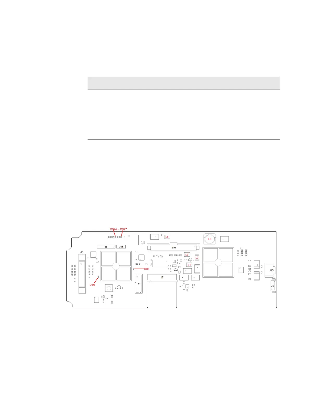
2. Referring to Figure 7-3, with the instrument turned off position the front
panel so that DS5, DS6, and DS24 through DS27 can be viewed.
Figure 7-3 A6A1 Status LED and Power Supply Voltage Measurement Locations
3. Turn the instrument on and monitor the status of the LEDs mentioned in
step 2 as the initialization routine is performed.
If the initialization routine runs properly, DS6 (red) will come on for a very
short period of time and then go off. DS24 through DS27 (yellow) will
come on and stay on. When DS6 turns off DS5 (green) will begin to blink.
Table 7-3 A6A1 Front Panel Interface Status LEDs
LED Function Normal Operation
DS5 Heartbeat of communication
between the keypad controller and
the instrument.
Blinking at approximately 24 Hz
once the keypad controller is out of
reset.
DS6 Keypad controller is in reset. Off when the controller is out of
reset.
DS24-DS27 Vertical sync delay CPLD status On
 Loading...


