258 Keysight CXG, EXG, and MXG X-Series Signal Generators Service Guide
Baseband Generators
A2 Vector BBG Assembly Troubleshooting
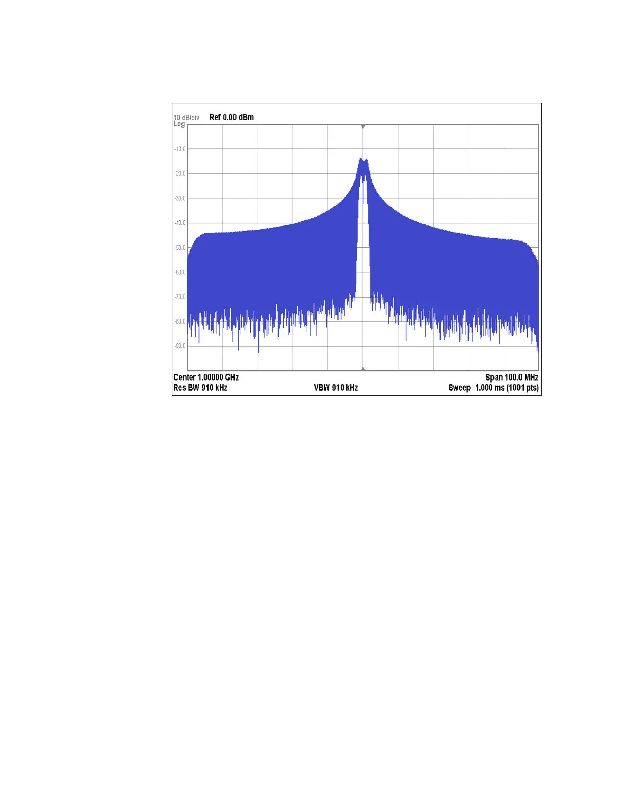
Figure 12-9 BNC Inputs Gated Waveform
17.Select the EVENT 1 input by pressing Patt Trig 1 BNC Source, Event 1.
18.Connect the function generator output to the EVENT 1 connector.
19.The signal on the spectrum analyzer should now be alternating between
the CW signal and the playing of the waveform file shown in Figure 12-9 at
a rate equal to the frequency of the function generator.
20.Select the BB TRIG 1 input by pressing Patt Trig 1 BNC Source, BB
Trigger 1.
21.Connect the function generator output to the BB TRIG 1 connector.
22.The signal on the spectrum analyzer should now be alternating between
the CW signal and the playing of the waveform file shown in Figure 12-9 at
a rate equal to the frequency of the function generator.
23.Select the BB TRIG 2 input by pressing Patt Trig 1 BNC Source, BB
Trigger 2.
24.Connect the function generator output to the BB TRIG 2 connector.
25.The signal on the spectrum analyzer should now be alternating between
the CW signal and the playing of the waveform file shown in Figure 12-9 at
a rate equal to the frequency of the function generator.
26.If any of the inputs are not gating the playing of the waveform, replace the
A2 Vector BBG assembly.
 Loading...


