62 Keysight E4980A/E4980AL Precision LCR Meter
Troubleshooting
Function Specific Troubleshooting
4-
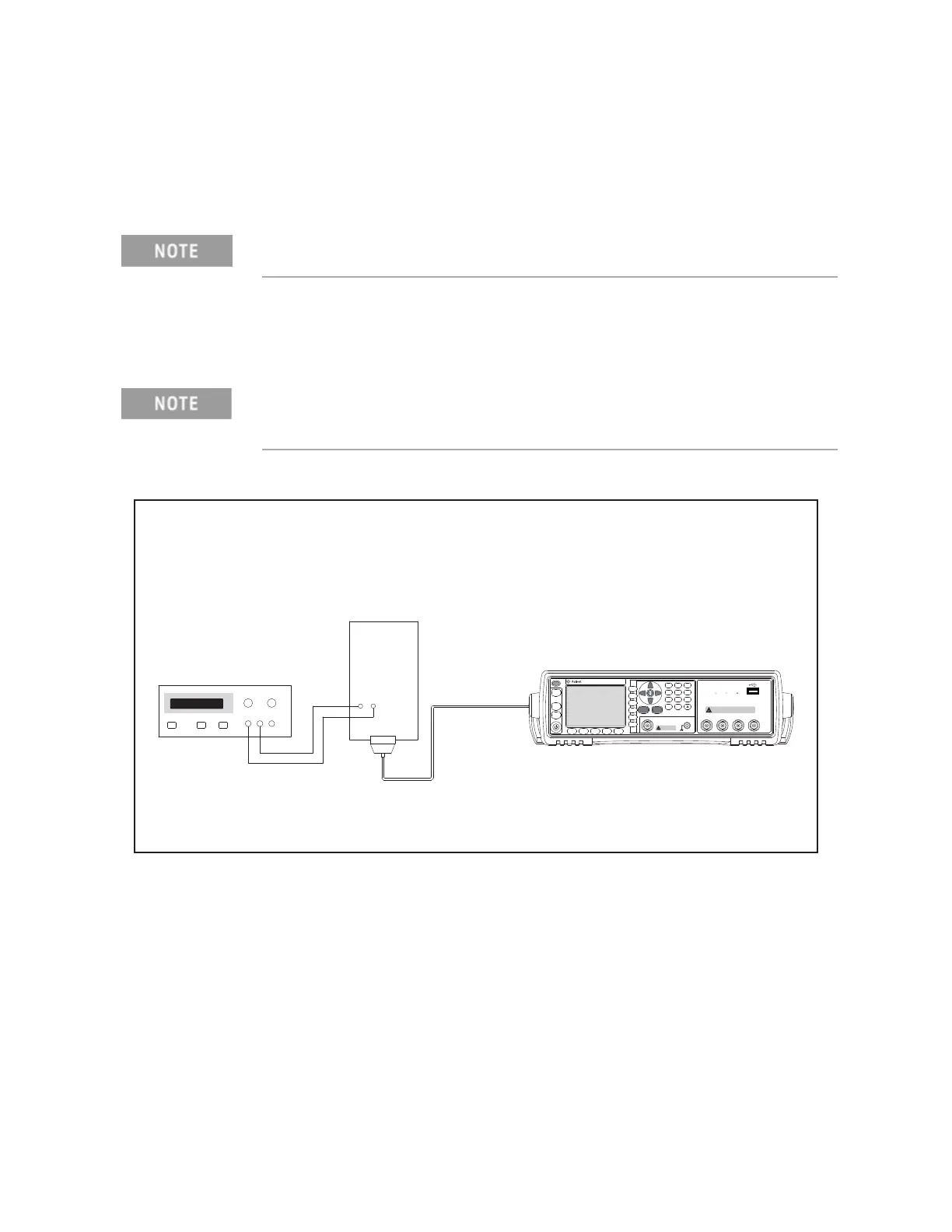
Step 2. Set DC power supply output voltage +5 V. Connect TP2 (GND) on the bias
interface simulator to ‘-’ terminal of the power supply. Then connect TP1
(Vcc) on the simulator to ‘+’ terminal of the power supply. (refer to Figure
Figure 4-15 and Figure 4-16.)
Step 3. Interconnect the bias interface simulator and bias interface connector on the
rear panel of the E4980A/ E4980AL with the bias interface cable as shown in
Figure 4-16.
Figure 4-16 Bias Current Interface Function Test Setup
Step 4. Turn the E4980A/ E4980AL ON.
Step 5. Press [System].
Step 6. Press the SELF TEST softkey to display the SELF TEST page.
Step 7. Use the CURSOR arrow keys to move the cursor to the TEST MENU field.
DC power for the bias interface simulator can be supplied from the
E4980A/ E4980AL instead of from an external DC power supply.
Connect using the adapter between the bias interface connector on the
rear panel of the E4980A/ E4980AL and the bias interface cable, when you
execute this step.
㪼㪋㪐㪏㪇㪸㫊㪼㪈㪇㪋㪎
Precision LCR Meter
20 Hz - 2 MHz
DC
DC
UNKNOWN
Discharge test device before connecting
r42V Peak Max Output CAT I
DC Source
(Option 001)
Tri g g e r
DC Bias
DC
Sou rc e
Ret urn
789
456
123
0
.
Preset
Display
Format
Mea s
Set u p
Recall A Recall B
Save /
Rec a ll
System
Local /
Lock
㪛㪚㩷㪧㪦㪮㪜㪩㩷㪪㪬㪧㪧㪣㪰
㪙㪠㪘㪪㩷㪠㪆㪝㩷㪪㪠㪤㪬㪣㪘㪫㪦㪩
㪜㪋㪐㪏㪇㪘
㪫㫆
㪙㪠㪘㪪㩷㪚㪬㪩㪩㪜㪥㪫
㪠㪥㪫㪜㪩㪝㪘㪚㪜
㪚㫆㫅㫅㪼㪺㫋㫆㫉
62)0&
628EE

 Loading...


