22 S-Series Oscilloscopes Service Guide
3 Testing Performance
Input Impedance Test
This test checks the input impedance of the vertical inputs. A four-wire
measurement is used to accurately measure the 50 Ω and 1 MΩ inputs.
Specifications
• 1 MΩ ±1%
• 50 Ω ±3.5%
Procedure
1 Set up the multimeter to make a four-wire resistance measurement.
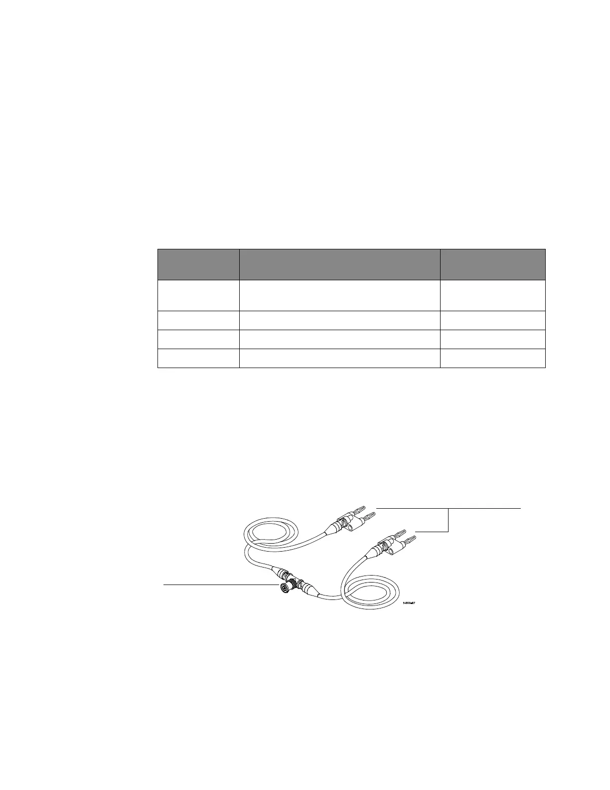
2 Assemble the test cables:
a Use the two BNC-to-banana adapters to connect one end of each BNC
cable to the four-wire resistance connections on the multimeter.
b Connect the free ends of the cables to the BNC tee as shown here.
3 Connect the male end of the BNC tee to the channel 1 input of the
oscilloscope.
4 Click Control > Factory Default to set the oscilloscope to default conditions.
5 Open the Channel dialog box for channel 1 (Setup > Channel 1...). Set the scale to
5 mV/div and set the channel input impedance to 50 Ω. Verify a resistance
reading of 50
Ω ±1.75 Ω.
Equipment Required
Description Critical specifications Recommended model or
part number
Digital Multimeter Measure resistance (4-wire) at better than ±0.1%
accuracy
34411A or 3458A
Cables (2) BNC 10503A
Adapter BNC Tee (m)(f)(f) 1250-0781
Adapters (2) BNC (f) to dual banana (m) 1251-2277
To DMM 4-wire
inputs
To oscilloscope
channel input
 Loading...


