70 S-Series Oscilloscopes Service Guide
4 Troubleshooting
Checking probe power outputs
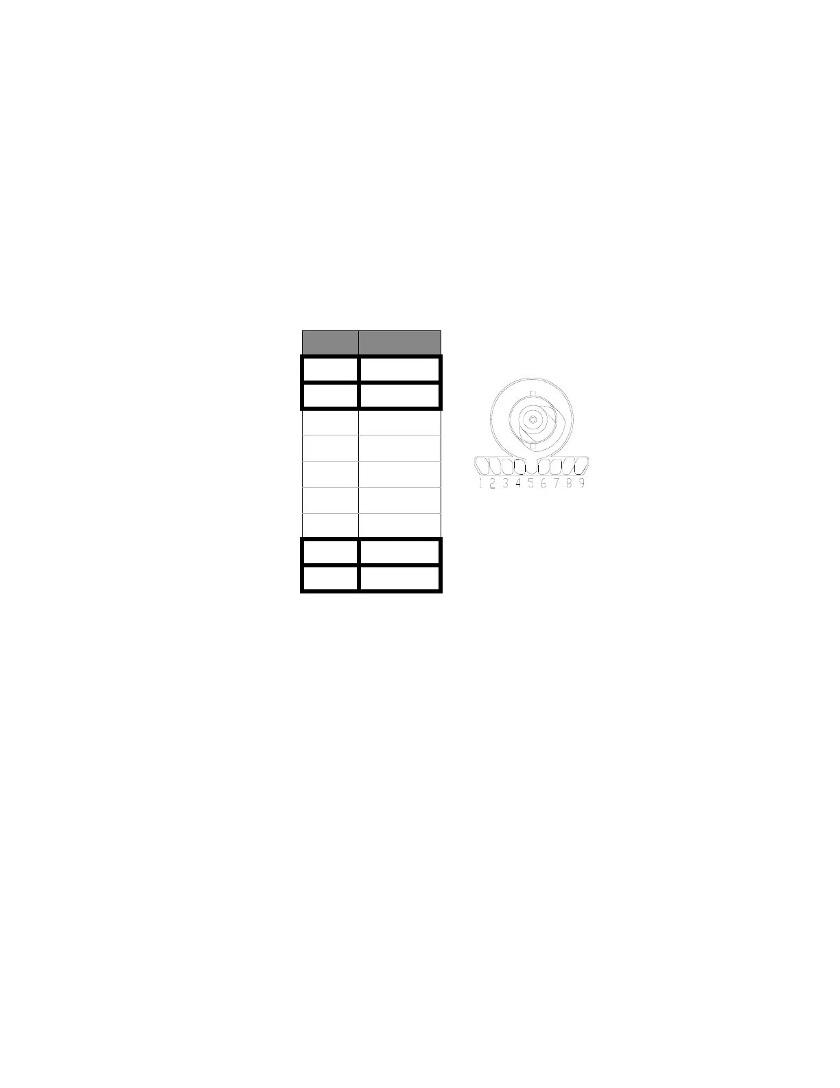
Probe power outputs are on the front panel, surrounding each BNC input.
Refer to the following figure to check the power output at the connectors. Measure
the +5 V, -5 V, +12 V, and -12 V voltages with respect to the Probe Comp ground
terminal on the front panel.
Do not try to measure voltages at pins 3 through 7.
Any failure is likely caused by a problem with the front panel board.
Pin Supply
1 +5 V
2–5 V
3 Offset
4Data
5 & ring Probe ID
6Clk
7Unused
8–12 V
9 +12 V
 Loading...


