The following is an example of how the bank indicator lamps work:
See the leftmost top and bottom pair of QSFP ports on the front panel and assume a configuration of 4
× 25G on each QSFP port (four MAC channels of 25G each). If you select the TOP bank, the four lamps
show the state of the top QSFP port's four channels from left to right as follows:
l QSFP Port 1/MAC Channel 1
l QSFP Port 1/MAC Channel 2
l QSFP Port 1/MAC Channel 3
l QSFP Port 1/MAC Channel 4
Port Status LED
The LED port channel status lamp indicates the following:
Color Port Status
Green Port/Channel is active (link is up)
Blue Port/Channel is enabled but the link is not up
Orange Port/Channel is disabled by an administrator
LED Off Port/Channel is not enabled or has not been added
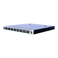
Rear Panel
The UHD100T32 100GE High Density 32-port QSFP28 rear panel image is as follows:
RS485 1 (Do not use)
RS485 3 (Do not use)
RS485 2 (Do not use)
GPI0 1 (Do not use)
Chapter 1 About UHD100T32
– 9 – 913-2626-01
 Loading...


