18 Keysight M8050A High-Performance BERT Getting Started Guide
1 Introduction
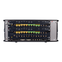
As displayed in Figure 5 on page -17, the M8042A module has the
following components.
Table 3 Front Panel LEDs
Table 4 Insertion/Extraction and Retaining
M8042A Front Panel Connectors
The M8042A pattern generator module provides many supplementary
inputs and outputs. Shown here is the overview of all inputs and outputs
for a two-channel version of M8042A.
Front Panel LED Active when... Color
Fail power-up fault condition red
Access power-up ready state green
Component Description
Retaining screws The screws on both ends of the module are used to retain the module tightly
inside the M9505A AXIe Chassis slot once you have fully placed it inside the
chassis. To remove the module, you first need to loosen these screws ensuring
that these screws disengage completely.
Module Insertion/Extraction
Handles
The handles on both sides of the module to insert or eject the module from the
slot of the M9505A AXIe Chassis.
The inputs of the M8042A module are sensitive to static electricity.
Therefore, take necessary anti-static precautions, such as wearing a
grounded wrist strap, to minimize the possibility of electrostatic damage.