Keysight NFA Series Noise Figure Analyzers Service Guide 163
RF Section Troubleshooting (N8973B, 74B, 75B Analyzers)
Troubleshooting
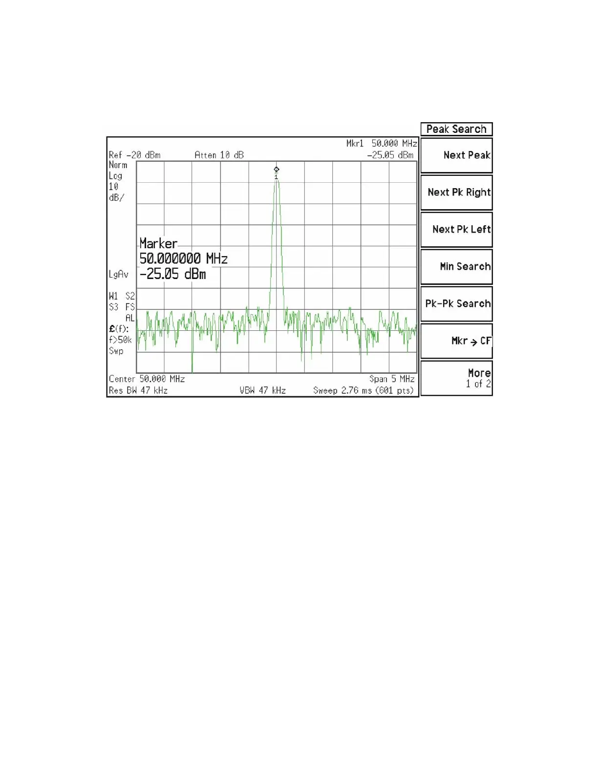
The level should be −25 dBm ± 2 dB as shown in Figure 4-14.
Figure 4-14 50 MHz Calibrator Signal on Output of Attenuator A
Press Mech Atten and enter 2 dB. The 50 MHz calibrator signal measured on
the functioning Spectrum Analyzer should measure 2 dB lower than the
previous step (~−27 dBm). Press Mech Atten and enter 4 dB. The 50 MHz
calibrator signal measured on the functioning Spectrum Analyzer should
measure an additional 2 dB lower than the previous step (~−29 dBm). If the
power levels measure correctly, reconnect W11 cable. If either of these levels is
incorrect, Input Attenuator A is the most probable cause, provided the control
logic from the A15 Front End Control Assembly was previously verified.