Keysight NFA Series Noise Figure Analyzers Service Guide 167
RF Section Troubleshooting (N8973B, 74B, 75B Analyzers)
Troubleshooting
If the power levels measure correctly, reconnect the W9 cable and reset the
input attenuation to 10 dB by pressing Mech Atten, 10 dB on the analyzer.
If either of these levels measure incorrectly, Input Attenuator B is the most
probable cause, provided the switch control logic has been verified.
Low Band Switch Power Level Verification
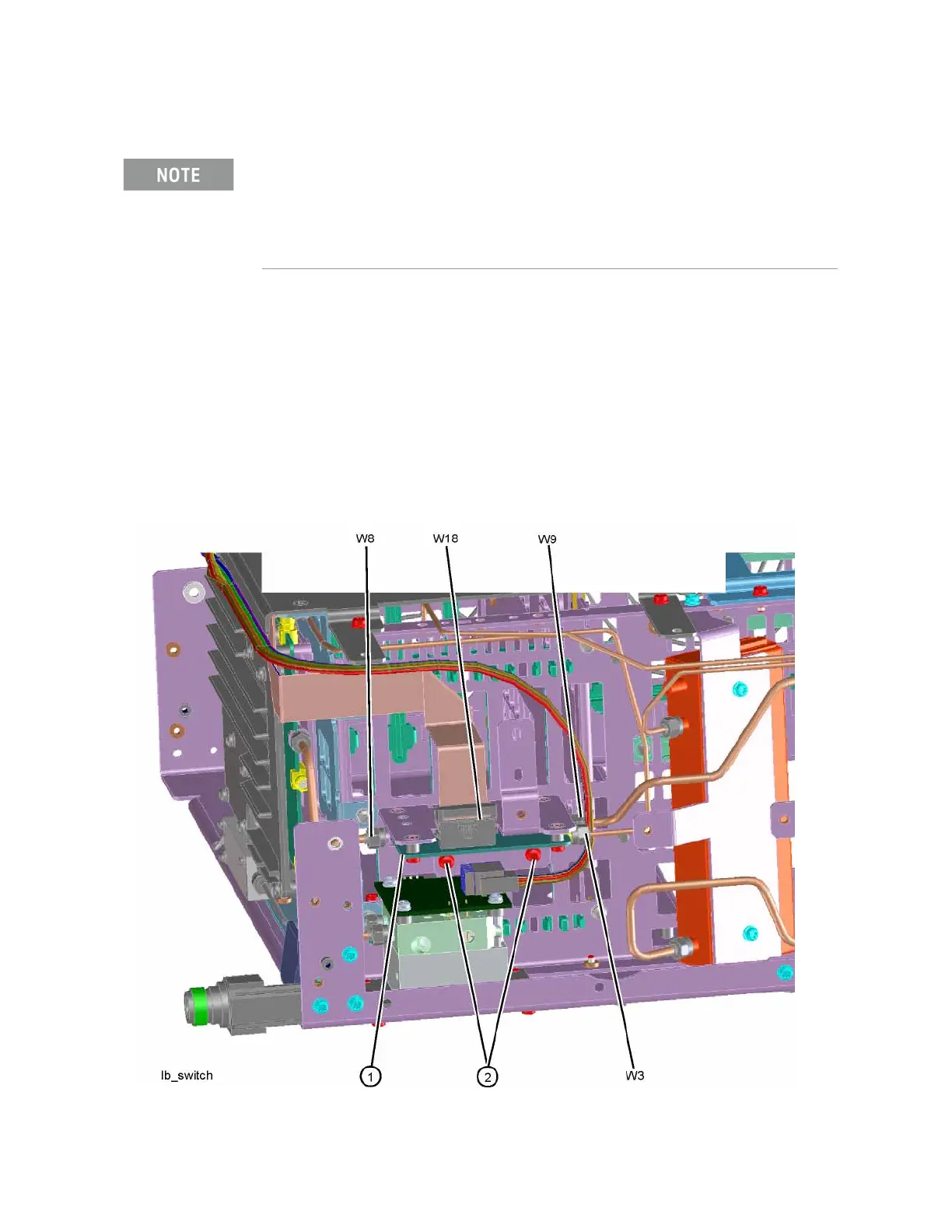
Refer to Figure 4-17. Disconnect the W3 cable at A11J2 of the A11 Low Band
Switch (1).
Figure 4-17 Cable W3 Location
1. It may be difficult to measure the higher attenuator settings using the
-25 dBm internal calibrator signal. Use an external source with the
frequency set to 50 MHz and adjust the output level to 0 dBm. This will
increase the measured power levels noted in the table above by 25 dB.
2. Tolerances should be used as a guideline.