Keysight NFA Series Noise Figure Analyzers Service Guide 189
RF Section Troubleshooting (N8973B, 74B, 75B Analyzers)
Troubleshooting
If any of the voltages measured do not match the levels in Table 4-17, the most
probable cause is the A15 Front End Control Assembly. Once the switch control
logic has been verified, turn off the instrument. Disconnect the RF Front End
Troubleshooting board cables, and reconnect the analyzer cables to the A15
Front End Control Assembly. Turn the instrument on and allow it to complete
its full boot up process to Spectrum Analyzer mode.
Input Attenuator A Power Level Verification
Press MODE/MEAS, Spectrum Analyzer, OK, Mode Preset, Input/Output, RF
Calibrator, 4.8 GHz, AMPTD, Attenuation, Mech Atten, 0 dB on the analyzer.
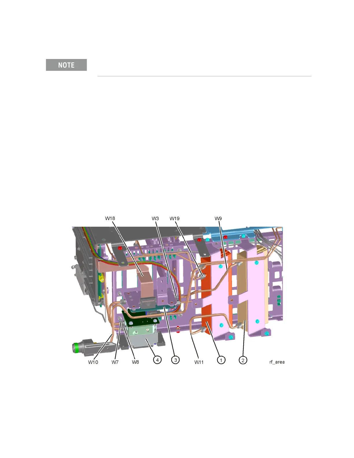
Refer to Figure 4-30, remove cable W11 from A9 (1) Output. Measure the
4.8 GHz calibrator signal on the output of the attenuator using the proper high
frequency cables and connect to the functioning Spectrum Analyzer.
Figure 4-30 W9 and W11 Location
Tolerances should be used as a guideline.