Keysight NFA Series Noise Figure Analyzers Service Guide 265
Analog/Digital IF Troubleshooting
25 MHz BW IF Section
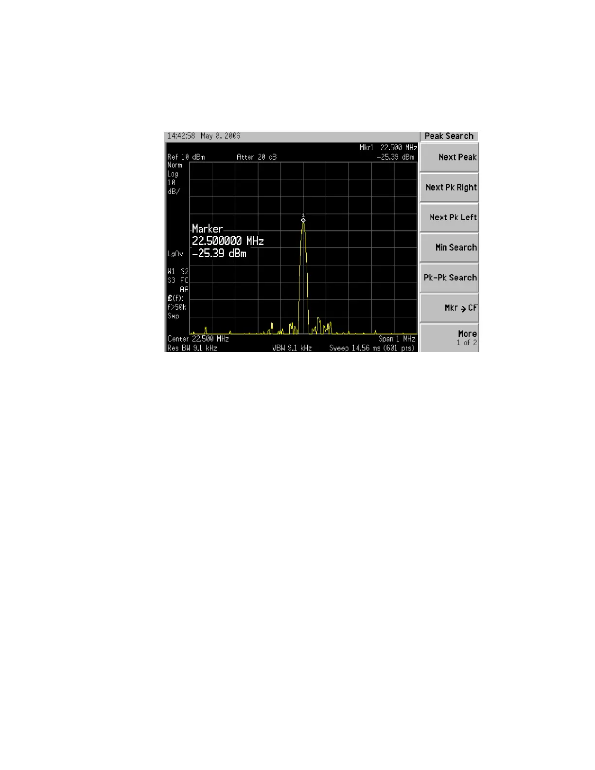
12.The analyzer should read 22.5 MHz at −25 dBm ± 4 dB as shown in Figure
7-8.
Figure 7-8 A3 Digital I.F. Input
If the 22.5 MHz signal is not measuring the correct power level, see “A2
Analog I.F. Troubleshooting” on page 253 in this service guide.
Verifying the 10 MHz Reference Input
1. Perform an instrument shut down.
2. Remove the cover of the analyzer. Refer to Chapter 15, “Assembly
Replacement Procedures”, on page 389 in this service guide.
3. Turn the instrument over so that the bottom is facing up.
4. Turn on the analyzer and wait for the instrument to complete the boot up
process.
5. Press System, Alignments, Auto Align, Off.
6. Press Input/Output, RF calibrator, 50 MHz.
7. Verify the 50 MHz signal is at −25 dBm by pressing MODE/MEAS,
Spectrum Analyzer, OK, FREQ, 50 MHz, Span, 1MHz, Peak Search on the
analyzer. The marker readout should be 50 MHz at −25 dBm ± 3 dBm. If
this reference signal is measuring incorrectly, see Chapter 4, “RF Section
Troubleshooting (N8973B, 74B, 75B Analyzers)”, on page 133 in this
service guide.