Keysight N9010B EXA Signal Analyzer Service Guide 193
RF Section Troubleshooting (RF/Microwave Analyzers)
Troubleshooting
Low Band Switch Power Level Verification
(for High Band)
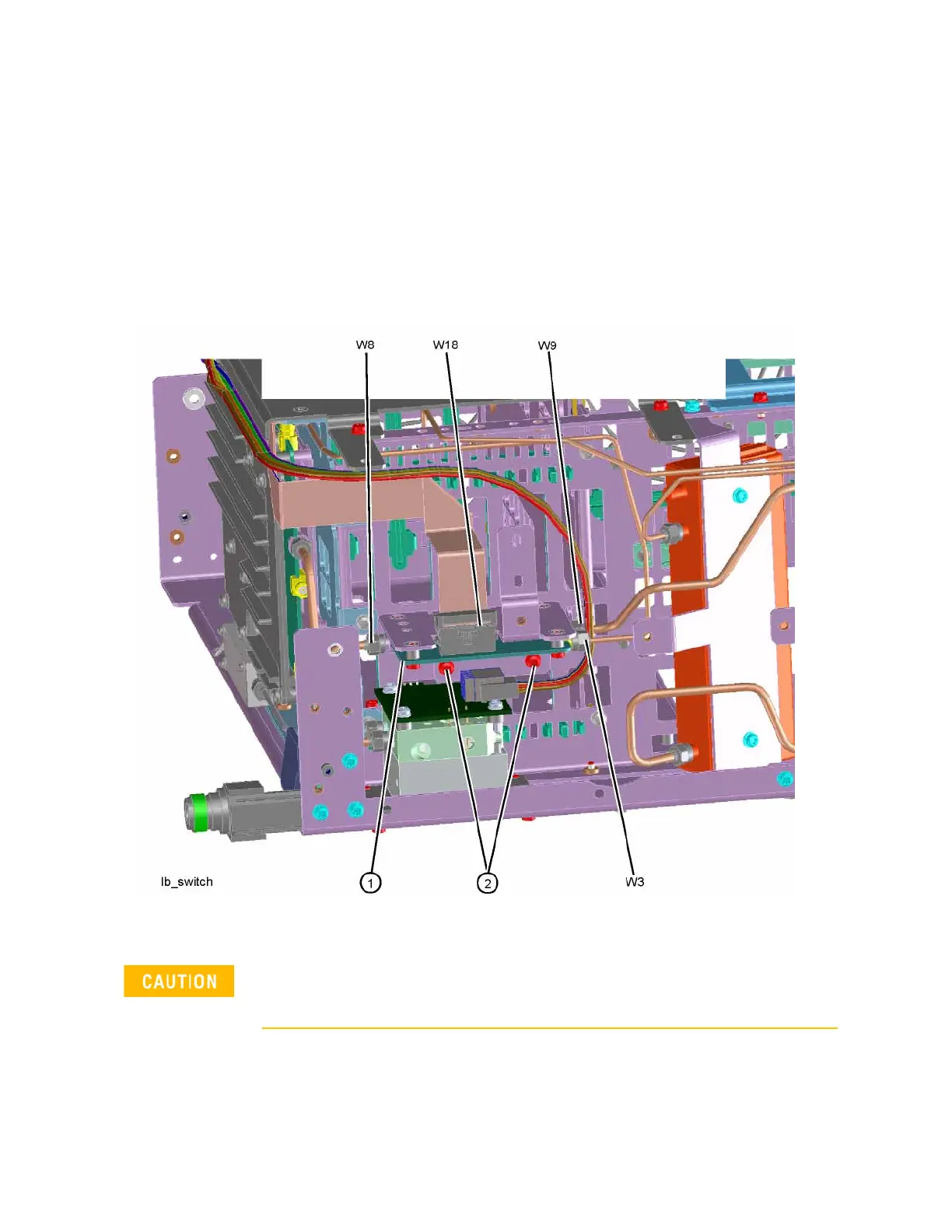
Refer to Figure 4-33. Carefully disconnect both ends of the W8 cable at A11J3
and A12 (1) input. If the microwave preselector bypass hardware is installed,
disconnect both ends of W31 at A11J3 and SW2 port C.
Figure 4-33 W8 Location
Press Input/Output, RF Calibrator, 4.8 GHz, AMPTD, Attenuation, Mech
Atten, 10 dB, FREQ, 4.8 GHz, Zero Span on the analyzer.
Be careful not to short out components on the front panel interface board
or the components on top of the A12 YTF Preselector when removing W8
or W31.