EasyManuals Logo

Keysight N9010B Service Manual

Keysight N9010B
598 pages
To Next Page IconTo Next Page
To Previous Page IconTo Previous Page
Page #454 background imageLoading...
Page #454 background image
454 Keysight N9010B EXA Signal Analyzer Service Guide
Assembly Replacement Procedures
RF Area (Option 503, 507, 513, 526)
Low Band Switch - Standard RF/Microwave Instruments
Removal
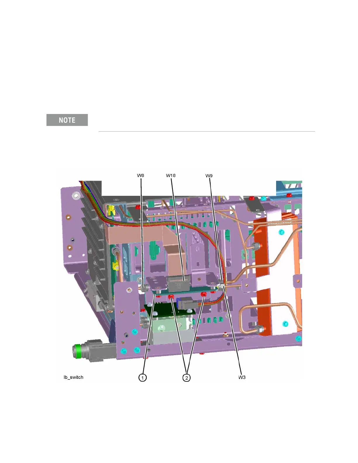
1. Refer to Figure 15-10. Remove the ribbon cable W18.
2. Remove the semi-rigid cables W3, W8, and W9 using the 5/16 inch
wrench.
3. Remove the two screws (2) using the T-10 driver. The low band switch
(1) can now be removed from the chassis.
Figure 15-10 Low Band Switch Removal
W8 will not be present in instruments with Option 503.

Table of Contents

Other manuals for Keysight N9010B

Questions and Answers:

Question and Answer IconNeed help?

Do you have a question about the Keysight N9010B and is the answer not in the manual?

Keysight N9010B Specifications

General IconGeneral
BrandKeysight
ModelN9010B
CategoryMeasuring Instruments
LanguageEnglish

Related product manuals