Keysight N9010B EXA Signal Analyzer Service Guide 455
Assembly Replacement Procedures
RF Area (Option 503, 507, 513, 526)
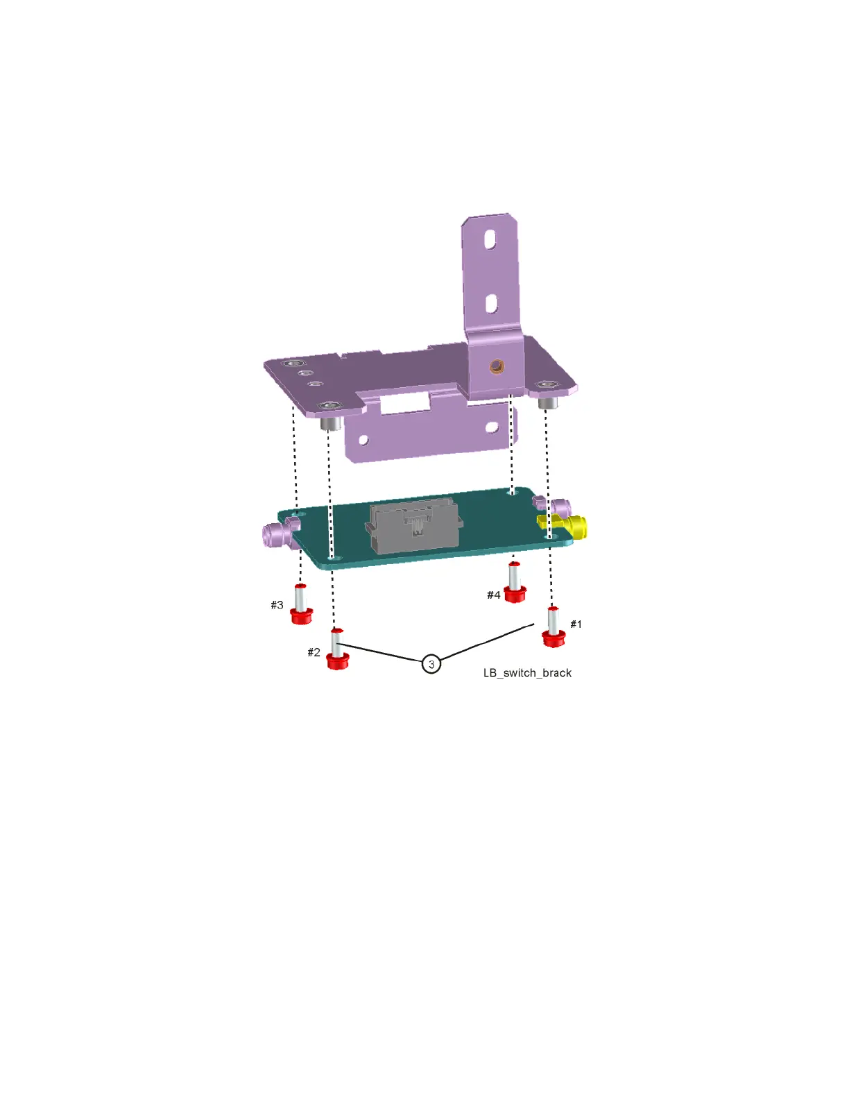
4. Refer to Figure 15-11. To separate the switch from the bracket, remove the
four screws (3) using the T-10 driver.
Figure 15-11 Low Band Switch and Bracket Separation