224 Keysight N9010B EXA Signal Analyzer Service Guide
RF Section Troubleshooting (Millimeter-Wave Analyzers)
Troubleshooting
To perform the YTF alignment, reconnect W46 or W7 cable, and press System,
Alignments, Advanced, Characterize Preselector. The routine may take
several minutes to align the YTF. Display the 4.8 GHz calibrator signal on
screen as explained in the quick check section. If the signal level is still
incorrect, suspect all assemblies, cables, switches and the A15 Reference
calibrator signal between the W46/W7 cable and the input to the A9
Attenuator.
If Option MPB is not present, remove A10 Input Attenuator B output cable and
measure the output power. Expected signal is 4.8 GHz −38 dBm. See Figure
5-11 for location of attenuator. If the attenuator output signal is correct
suspect the A11 Low Band Switch, and if Option MPB is installed, suspect
switch 4. Also suspect the switching signals from the A15 Front End controller.
The control signals are explained in the Front End Control Troubleshooting
section.
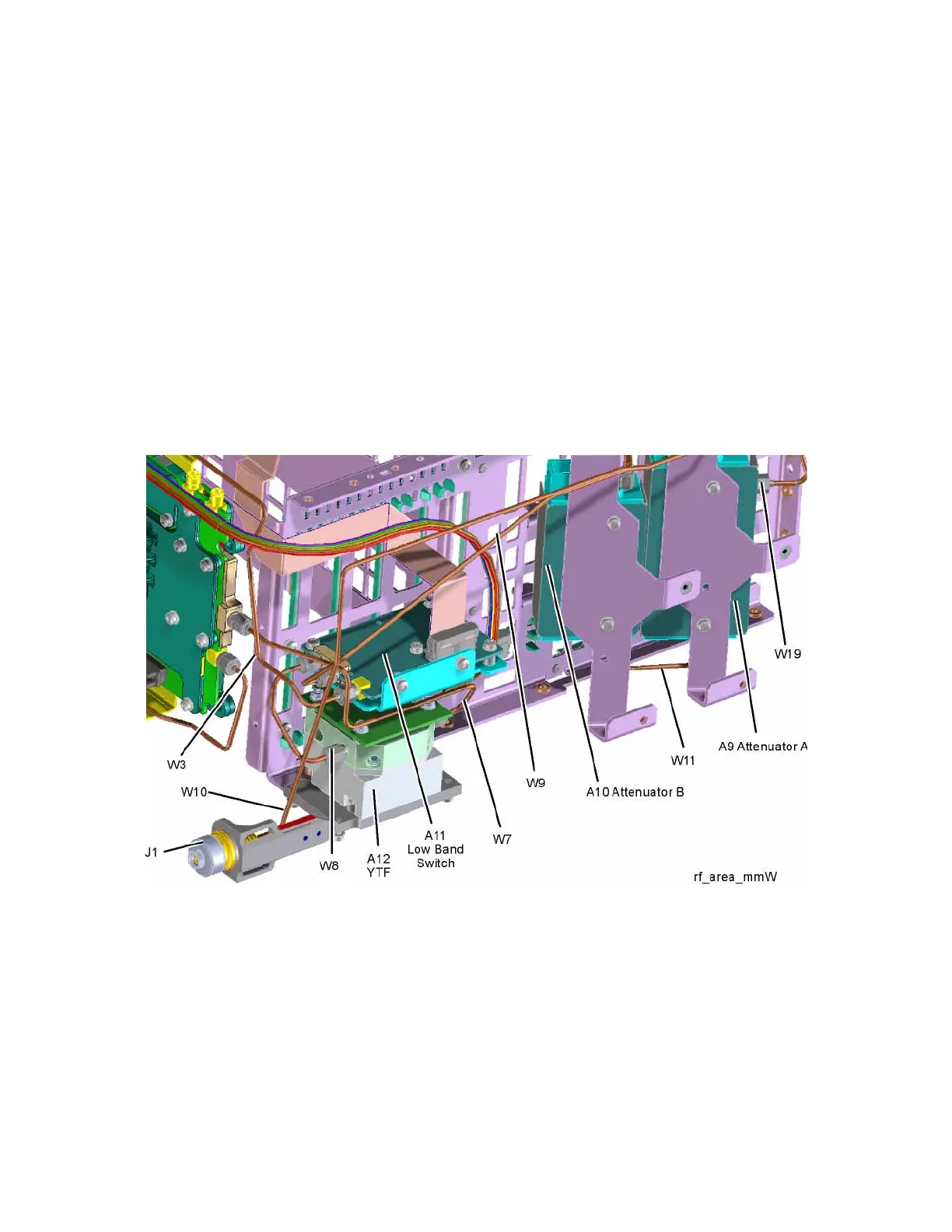
Figure 5-11 RF Section
A9 Input Attenuator A and A10 Input Attenuator B Verification
Calibrator Switch Test
On the A16 Reference assembly, disconnect semi rigid cable W19 from
A16J701 and measure A16J701 with a spectrum analyzer. Expected signal is
4.8 GHz at −28 dBm ± 0.5 dB. If signal level is incorrect, suspect A16 Reference
Assembly.