Installation
06-237619-001 4-33 April 2020
4-13 ELECTRICAL INSTALLATION
The cable routing plan shall include all electrical components including detailed loop
information and the cable quality to be used, such as; mm sq, rating IEC, braiding, twisted
cores, required material and color of the outer sheath, bending radius, max. distance between
supports/strapping, 90º crossing etc.
Also the cable routing plan shall include notes regarding maximum distances allowed for
parallel runs, minimum distances between control and power cables (normally 500 mm), and
separate cable ways/trays to be used etc.
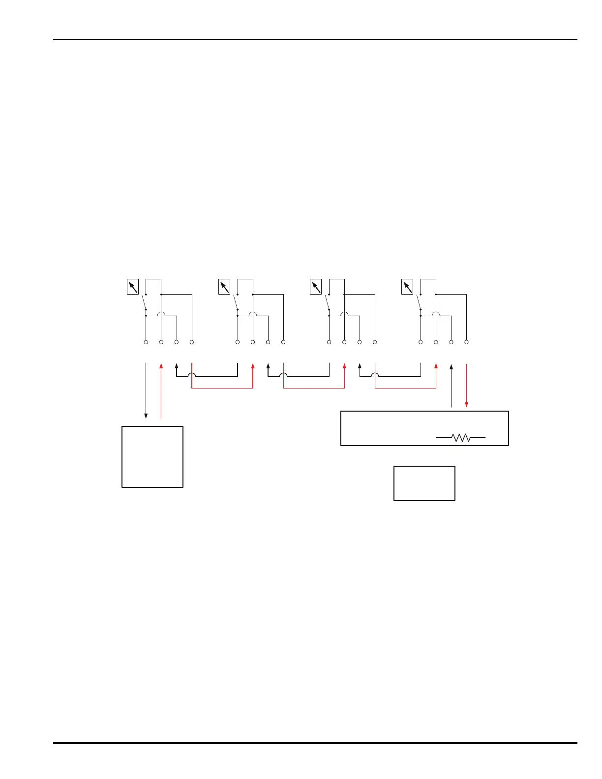
4-13.1 Release Unit/Slave Cylinder Gauge Assembly Wiring
Note: Release unit solenoids must be continuously powered during system discharge.
Connect the release unit/slave cylinder gauge assembly as indicated on the electrical wiring
diagram and terminate in the allocated terminals in the control panel/junction box.
The release units are wired separately. The slave cylinder gauge assembly should be connected
in a single loop configuration (between cylinders) using the quick connect cable joiners
provided.
Figure 4-23. Quick Connect Wiring Example
Control Panel
-
1
+
234
-
1
+
234
-
1
+
234
-
1
+
234
End Terminal
Plug
(38-400005-101)
38-400005-102
or
38-400005-103
&
End of Line Resistor (EOL)
or
38-400005-100 38-400005-100 38-400005-100
38-400005-105