Post-Discharge Maintenance
April 2020 7-2 06-237619-001
7-3 RE-INSTALLING RELEASE UNITS
Follow this procedure when re-installing the release unit:
Note: When reinstalling the release unit, the O-ring must be replaced.
1. If the release unit was operated manually or the tamper proof seal was removed, install a
new tamper proof seal.
2. Remove the old O-ring in the connecting swivel and replace it with one of the O-rings in-
cluded in the rebuild kit, P/N: 38-400001-010. Make sure the O-ring is properly lubricated
before installation. If lubrication is missing, use silicone spray (Würth Art no: 0893221 or
similar).
3. Install the release unit on the cylinder valve and tighten swivel nut by hand until pressure
is indicated on the gauge.
4. Secure the connecting swivel of the release unit by the use of an M36 A/F fixed wrench.
Apply a torque of 44.25 ± 0.75 ft lb (60 ± 1 N-m) on the unit. A counter hold may be re-
quired during tightening.
5. Leak test all connections on the release unit by means of ammonium-free leak detection
liquid or spray, ensuring that there is no leakage
6. Connect the actuation hose to the release unit, then to the cylinder valve. Make sure to
push the actuation hose in fully.
Figure 7-1. Actuation Hose Install
CAUTION
Only the O-ring should be lubricated. Excessive lubricant in the valve port will
enter into the valve itself when pressurized and may jeopardize the
performance.
Used O-rings that are removed are to be deliberately cut and discarded to
prevent inadvertent use.
CAUTION
Do not tamper with the release unit. Any adjustment to components pre-fitted
to the connector block will lead to a leak. After the release unit is pressurized,
do not adjust the alignment as this may reset the shredder valve in the cylinder
valve causing it to discharge or not seal properly.
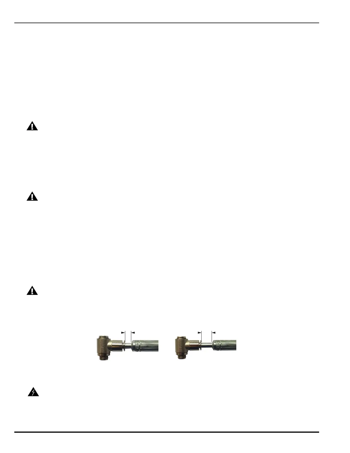
CAUTION
Ensure the actuation hose is fully inserted into the release unit. There should be
a gap of no more than 1/4” (6 mm) between the end of the festo connector and
the release unit quick connect.
WARNING
Never attach the release units to the cylinder valves until the cylinders are
secured in brackets or racking. Under no circumstances is the release unit to
remain attached to the cylinder valve after removal from service, handling,
storage, or during shipment. Failure to follow these instructions could result in
serious bodily injury, death, or property damage.
No Greater than 1/4” (6 mm)
CORRECT INCORRECT
Greater than 1/4” (6 mm)