Page 27
Stratos HSSD-2 • INSTALLER’S HANDBOOK • Iss. 12
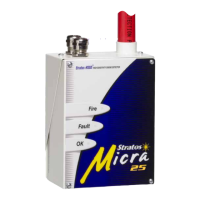
5.2 Mechanical
installation
The detector body is fitted to a wall-mounting bracket which is attached to the wall via
the mounting holes E as shown below. The detector is then fitted over the mounting
stud D and secured inside the detector body with the nut provided for the purpose.
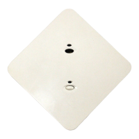
For a more discreet layout, it is possible to allow the sampling pipes and cables to
enter the detector from the rear (see illustrations below), with the sample pipes and
connection cables channelled into the wall. In order to achieve this, sampling holes A
and B need to be opened up to a diameter of 30mm to take the sampling pipes (A) and
the exhaust pipe (B). The holes C need to be opened up to 25mm diameter in order
to take a suitable threaded metal cable gland to provide adequate RF screening for the
connection cables. These modifications are shown in dotted lines below.
The wall will also need to be suitably prepared to allow the mounting plate to sit flush
against the wall. The sampling and exhaust pipes must also extend out of the wall
sufficiently to tightly engage in the pipe entries on the rear of the detector as shown.
A good starting point would be 25mm of pipe extending past the back plate. If the
detector then sits proud of the bracket, the pipe excess can be trimmed back in small
increments until the correct fit is achieved.
A.
E.
B.D.C.
Rear pipe
entry option
Top pipe
entry option
Fault O K
S
M
O
K
E
D
E
N
S
I
T
Y
Fire 2
Pre -Ala rm
Aux . Al arm
Fir e Al arm
5
15
20
25
1%
2
9
1
0
1
2
3
4
5
6
7
8
TEST
RESET
ISOL.
ENTER
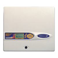
HI GH S E NS IT I VI TY SM OK E D ET EC T OR
2
COMMAND MODULE
Exhaust pipe
Sampling pipes