Page 28
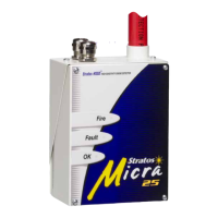
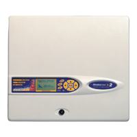
Stratos HSSD-2 • INSTALLER’S HANDBOOK • Iss. 12
5.2.1 Removal and
replacement of the
detector front cover
To remove the front cover, unlock it using the key provided (turn anticlockwise). The
bottom of the front cover may then be lifted away from the detector chassis until the
top of the cover disengages from the retaining rails at the top of the chassis. The cover
may then be removed.
If greater internal access is required, e.g. for software upgrades, it may be necessary to
remove the LCD display board. To do this, unfasten the four counter-sunk crosshead
screws holding the display to the display mounting brackets (NB, it is not necessary
to remove the remaining four screws - see sections 1.3, 1.4, 1.5) and lift the display
away from the main board. If the display needs to be completely removed, unplug the
display ribbon connectors from the detector or Command Module main board, taking
note of the position of the connectors which are as follows:
■
For the Standard Detector, a single ribbon cable connected to the detector’s ‘Front
Panel’ display connector (see section 1.3)
■
For the Command Module detector, a twin ribbon cable, one ribbon connected to
the detector’s ‘Front Panel’ display connector and marked ‘DISPLAY DET’, and one
connected to the Command Module board’s ‘Commander Display’ connector and
marked ‘DISPLAY COM’ (see sections 1.3 and 1.4).
■
For the stand-alone Command Module, a twin ribbon cable, one ribbon connected
to the ‘Detector Display’ connector and marked ‘COMMAND DET’, and one
connected to the ‘Commander Display’ connector and marked ’COMMAND COM’
(see section 1.5).
When completely removing the display it is recommended that the ribbon connectors
be removed from the main detector or Command Module board rather than from the
display board. When removing these connectors, ensure that suitable antistatic precau-
tions are taken, e.g. use of antistatic wrist straps, to prevent possible static damage to
the unit’s electronics. Refitting of the display is the reverse of the above procedure NB:
ensure that the connectors are refitted as described above.
To refit the front cover, hook the recessed lip at the top of the front cover behind the
two retaining guard rails at the top of the chassis like so:
Guard rails