58 PMC-A
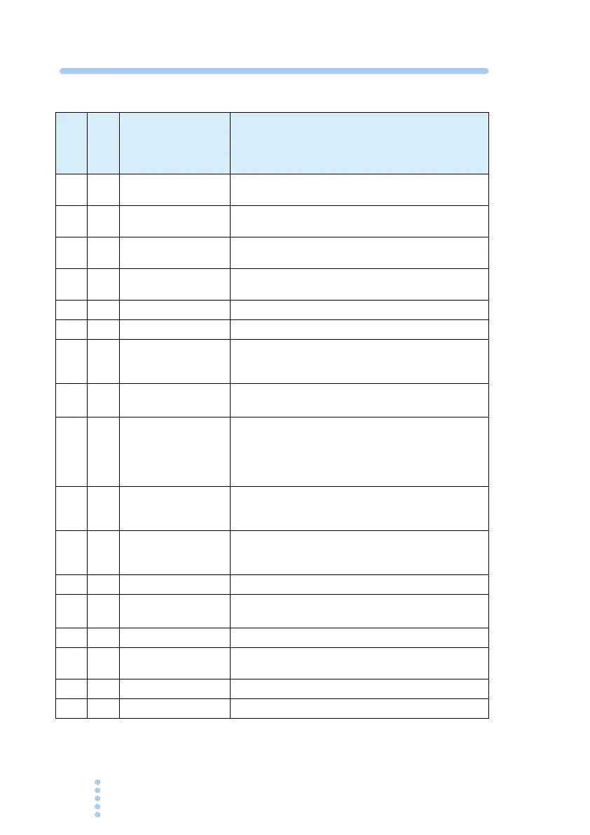
Table 5-3 Pin arrangement of the J2 connector
14
pins
type
*2
Pin
No.
Signal Name Description
- 1 CV STATUS
On during CV operation
(open collector output by a photocoupler)*1
- 2 CC STATUS
On during CC operation
(open collector output by a photocoupler)*1
- 3 V MON
Output voltage monitor (Outputs 0 % to 100 % of the
rated current using 0 V to 10 V)
- 4 I MON
Output current monitor (Outputs 0 % to 100 % of the
rated current using 0 V to 10 V)
- 5 N.C.
No connection
- 6 N.C.
No connection
1 7 EXT-V CV CONT
External voltage control of output voltage.
(0 % to 100 % of the rated output voltage using 0 V to
10 V).
2 8
EXT-R CV CONT
COM
Common for external resistance control of output volt-
age.
3 9 A COM
Common for external signal of pins 3, 4, 7, 15.
Connected to the negative electrode (-S) of the sens-
ing input when remote sensing is used.
Connected to -(neg.) output when remote sensing is
not used.
4 10 EXT-R CV CONT
External resistance control of output voltage.
(0 % to 100 % of the rated output voltage using 0 V to
10 V).
5 11 EXT-R CC CONT
External resistance control of output current.
(0 % to 100 % of the rated output current using 0 Ω to
10 k
Ω).
6 12 A COM
Same as pin 9.
7 13
EXT-R CC CONT
COM
Common for external resistance control of output cur-
rent.
8 14 A COM
Same as pin 9.
9 15 EXT-V CC CON T
External voltage control of output current.
(0 % to 100 % of the rated output current 0 V to 10 V).
10 16 NO CONNECTION
No connection
11 17 A COM
Same as pin 9.