Kinco-KS series
3.4.2 measure range and measure value for AI
The input signal in each channel will sample ADC and counter. The results will be send
to CPU AI area from expansion CAN. Then user programming can visit it.
All the signal types have detection range. If the value is over range, the modules will
warn, and the LED will be on. Meanwhile it will send problem file to CPU by expansion
module. Pls connect all the channels that is not used, also setup signal type to 【0-20mA】 or
【0-10V】,then these channels won’t warn.
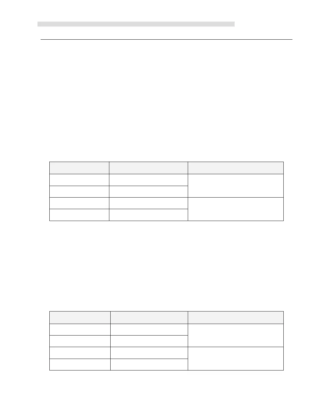
Below is detection range and value format. I is input current, V is input voltage.
3.4.3 AO output range and value format
AQ output will be send AO modules by expansion bus, then counter and change. After that it
will output from channel by DAC.
The output range of all signal types is limited. If the output is over range, the output will keep
the up/down limited value.
Below form is output range and value format., I is real current, V is real voltage

 Loading...

