Kinco-KS series
Starting value of preset value table ( It is
offset corresponding to VB0),it must be odd
value.
It needs to pay attention that not all the control bits of the control byte is suitable for all
operation mode. For example, “Counting direction” and “Write counting direction in HSC”
can be only used in mode 0,1 and 2 (Single-phase up/down counter
with internal direction control),if the operation mode is with external direction control, then
these two bits will be ignored.
The control byte, current value and preset value are 0 by default after power on.
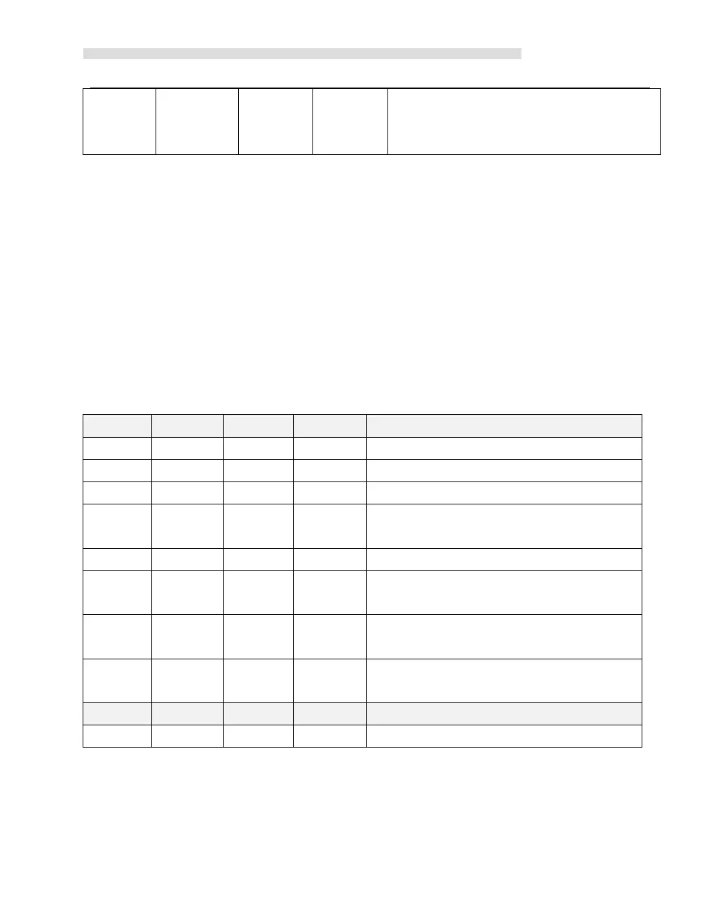
In SM area, each high-speed counter has a status byte, which indicates the current status
of high speed counter.
Fault in multiple PV value
table:0=No,1=Yes
Current counting direction:
0 = Down; 1= Up
Current value equal to preset value:
0 = No,1 = Yes
Current value greater than preset value:
0 = No,1 = Yes
Current PV segment No.(Start from 0)
4.2.3 Preset value (PV value) setting
KS supports up to 32 PV value for each high speed counter, and supports setting PV value as
 Loading...


