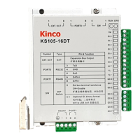
Kinco-KS series
2K bytes. Lithium battery ,3 years at normal environment
256
1ms :4
10ms :16
100ms :236
yes,the difference is 5 min/month at 25℃
2.2 Functions
2.2.1 CPU Status and LEDs
The CPU has two modes: STOP mode and RUN mode.
In RUN mode, the CPU executes the main scan cycle and all interrupt tasks.
In STOP mode, the CPU will set all output channels (including DO and AO) to the known
values which are specified in the [Hardware Configuration] through Kincobuilder, and only
process communication requests which comes from KincoBuilder software and other
Modbus RTU master device.
Kinco KS provides two ways for manually changing the CPU status: Using the operation
switch (RUN/STOP); Executing [Debug] -> [RUN] or [STOP] menu command in
Kincobuilder.
Usually when the PLC is power on, the PLC status is based on switch and Kincobuilder

 Loading...