should be near the signal of system under test. The cable between the logic analyzer and the system
under test should not be long, because long cables would result in heavy inductive effect and signal
reflection. Therefore it is recommended that in debug stage of the system some pins should be
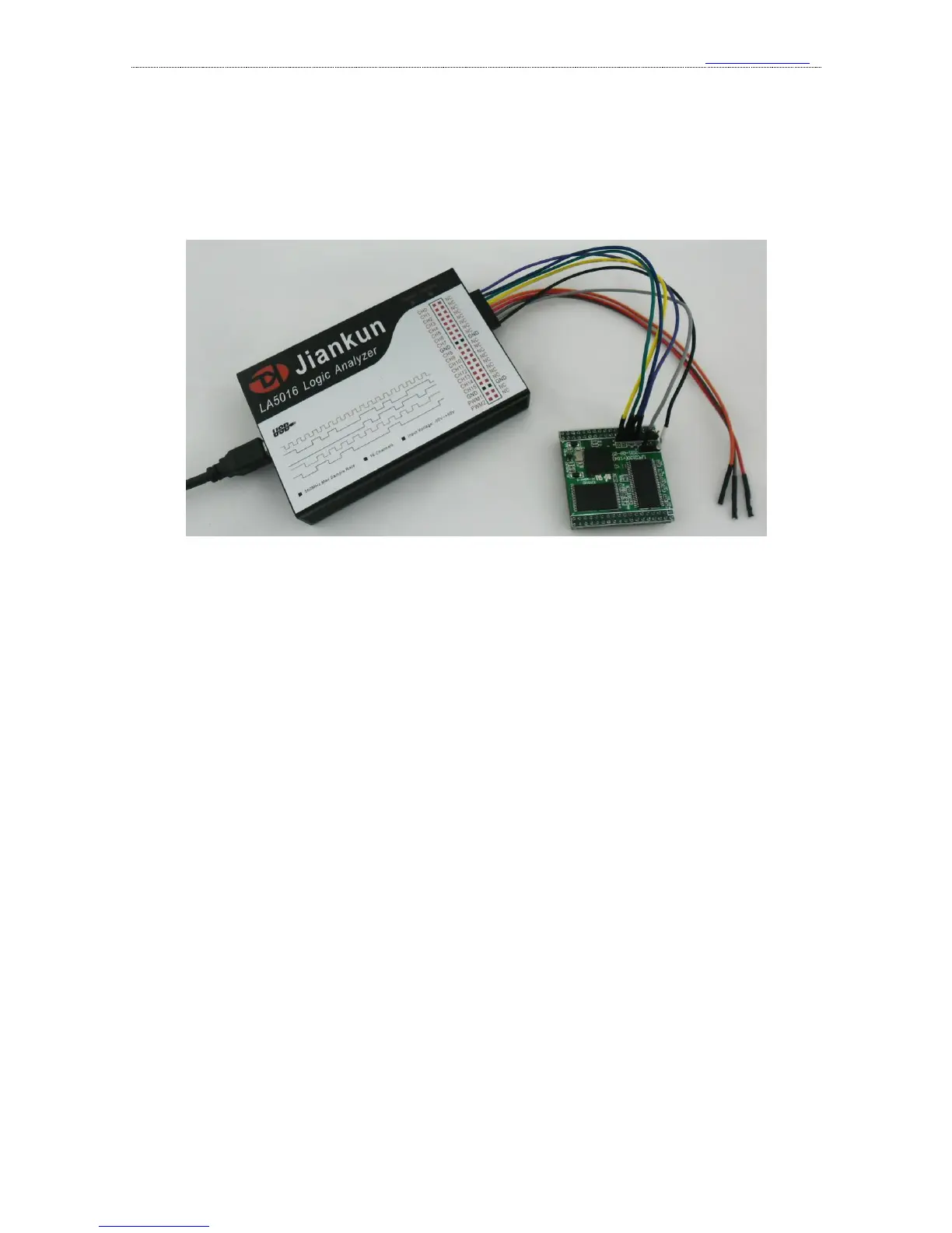
reserved on the experiment board to make the best of measurement. The connection between the
logic analyzer and the system under test is shown in the figure below:
3、 Multipoint grounding to increase accuracy
when measuring multiple channels with high frequency signal, the signal current from all
channels would flow into the system under test through GND channel, and the inductive effect of
the wire in high frequency is strong, so signal current of multiple channels would overlap on GND
channel, and as a result of that, the instantaneous voltage difference would be too large to result in
the “glitch” on the waveform under test.
To remove these “glitches”, we could take the multipoint grounding method. Normally the
logic analyzer would provide several GND channels. If we connect these channels to the grounding
point of the system under test, the signal current which we have mentioned would be divided into
different path, and the “glitch” could also be removed. The multipoint grounding mainly includes:
①. Direct connection——GND channel of the logic analyzer should be connected to the GND
wire of the system under test directly.
②. Dispersed connection——the GND channels should be connected to different parts of the
system under test. Multiple GND channels should not be connected to one grounding point of the
system.