V. Settings for standard protocols
1、 UART/RS232/485
For standard UART, RS232 and RS485, they have the same timing definitions of the physical
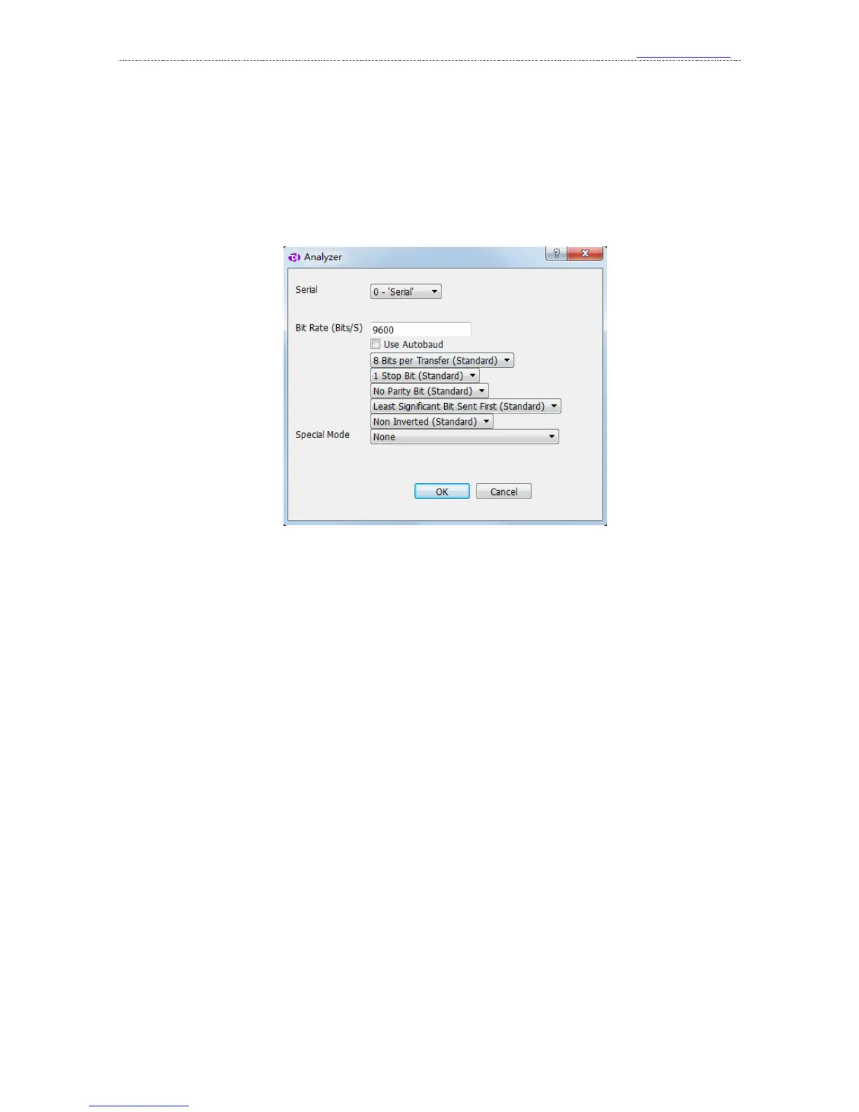
layer, so they share the same analyzer, and the figure below shows the setting dialog of
UART/RS232/485 analyzer.
1
st
item, select the channel to use.
2
nd
item, set the baud rate, and the baud rate here should match that in actual use.
3
rd
item, use the auto baud, and the software could identify the baud rate automatically. In case
of the baud rate is unknown, this option should be enabled. But the accuracy of automatic
identification depends on actual signal, and the result could be incorrect.
4
th
item, select the number of data bits, and it is 8 most of the time.
5
th
item, select the number of stop bits, and there are 3 options: 1, 1.5 and 2.
6
th
item, set the parity bit, and there are 3 options: no parity, even parity and odd parity..
7
th
item, set the bit order in data transfer, and the options could be LSB(Least Significant Bit
Sent First) and MSB(Most Significant Bit Sent First).
8
th
item, invert the data or not. Normally Inverted is only used for RS232(As For RS232,
positive level is 0 and negative level is 1) and Non Inverted could used for UART and RS485.
9
th
item, set bit 9 as address flag in multiple machine communication or not, and by default,
None. When this mode is actually used (seldom used, note that it is different with RS485 multiple
machine communication), it could be used for address byte flag.
Please note that if the signal under test is differential signal like RS485 and RS232, there are 3
ways to connect the wire:
①. The GND channel of the logic analyzer is connected to the GND of the test system, and 2
signal channels are connected to RXD and TXD pins of the level shift chip respectively .
②. The GND channel of the logic analyzer is connected to the GND of the test system, and 1