not be continuous, and the user can not tell when it would occur, such as UART communication. In
this way, maybe we could not sample any effective data during the time since we pressed “start”.
To solve this problem, we could utilize the trigger function.
First we set a certain condition, and then when the signal meets the condition, the data sample
would start. This is how trigger works, and the conditions here are trigger conditions, such as jump
edge of the signal, high/low level or the combinations of them. The trigger conditions should be set
based on the characteristics of the signal to test, for example, in UART communication, for the idle
state in which no data are transferred, the signal is high level, and every UART data frame is started
by the transfer from idle state to start bit, which is low level, so we should set the falling edge of
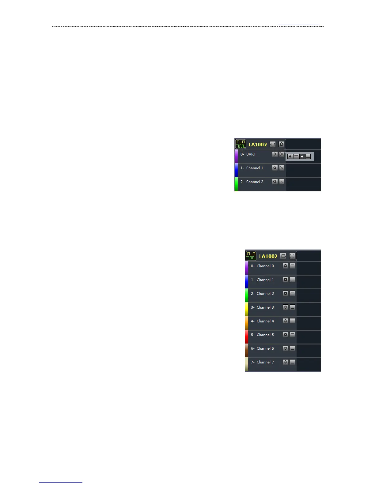
this channel as the trigger condition. If the channel 0 is used for
UART signal, as the right figure shows, we could press the
button on the right side of channels settings bar of channel 0, and
select the 3
rd
button of the popped toolbar which represents
“falling edge”. If we want close the toolbar, we could click other
positions of the screen.
After the trigger is set and the button “start” is pressed again, if the trigger condition (falling
edge) we have set have not appeared on channel 0, the logic analyzer would stay in wait state until
the falling edge arrives. Then the device will sample and save the data, and upload the data to the
computer for displaying and analyzing when the process is complete.
Except the edge and level trigger condition for single channel,
the logic analyzer also supports the condition combinations of
multiple channels, such as levels, one edge and multiple levels. The
final condition is the “logical AND” of these conditions, which
means the sampling process starts when all conditions are met. In
this way, the trigger can be the result of certain parallel data. It could
be used in the situation when the master device like MCU accesses
the peripheral through the bus and we want to check the data
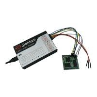
write/read operations of a certain address. For example, if we want to
check the data operations of address 0x35, channels 0-7 should be
connected to 8 address lines, and the other channels are connected to
the data lines. After we set the level combination of channel 0-7 as
the trigger condition, the data in this address could be sampled. The trigger settings are shown in
the right figure.
3、 Get the waveform
After the basic settings we mentioned above have been made, we could begin sampling the
signals that we need. The sampling process is started by pressing the “start” button. The logic
analyzer samples the signal since then (trigger conditions should be met if they are set), and stops if