III. Connect the device
1、 Connect the device to PC
When the installation process is completed, the logic analyzer can be connected to PC through
the attached USB cable (In case of desktop computer, use the USB port behind the tower box).
Then the computer would report that new hardware has been found. In Windows XP, there would
appear a driver installation dialog, and just select to install automatically. In Windows 7/8/10, a
dialog would appear in the top right corner of the screen. Then the install process would start
automatically, and we just need to wait for a while. After the installation process is completed, a
new device called “Kingst Instrument-Logic Analyzer” would appear in “Device
Manager->Universal Serial Bus”.
After the device is connected to PC and the driver has been
installed, the device would be connected automatically when we
open the software. When the connection is complete, as shown in the right figure, the device bar on
the top left side of GUI would display current device type. The icon on the left side means that the
current device is a logic analyzer. And through the two buttons on the right side, you could select
other devices or change the settings of current device. The detailed information would be
introduced in chapter 4.
Besides, the status bar of the bottom left side shows the connection status of current device.
“Device connected” means the device hardware has been connected to PC successfully and ready
to work, while “Device unconnected” means the device hardware is not connected to the USB port
of PC, or because there is something wrong, the device could not work normally.
2、 Connect the device to system under test
Please note that the logic analyzer and the computer share the same ground, so the voltage
between the GND of system under test and the GND of the computer should be zero. Especially
when the system is connected to the force electricity, please make sure the isolation is made. If
devices with force electricity like frequency transformer are not isolated through the isolation
transformer, the system would be connected to the force electricity. And if you connect the logic
analyzer to such a system, the logic analyzer even the computer would be broken. And the damage
could be beyond repair, so the isolation should be made in advance.
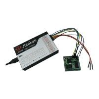
When the logic analyzer is connected with the system under test, you should first connect the
GND channel to the system under test, and then connect the signal channels. There are 16 channels
in the logic analyzer. It means that up to 16 digital signals could be tested simultaneously. If the
number of existing signal is less than 16, the channels could be selected at will. The channel
numbers of the software correspond to that of the hardware device.
In addition, when measuring the signal with high speed, the measuring lines of logic analyzer