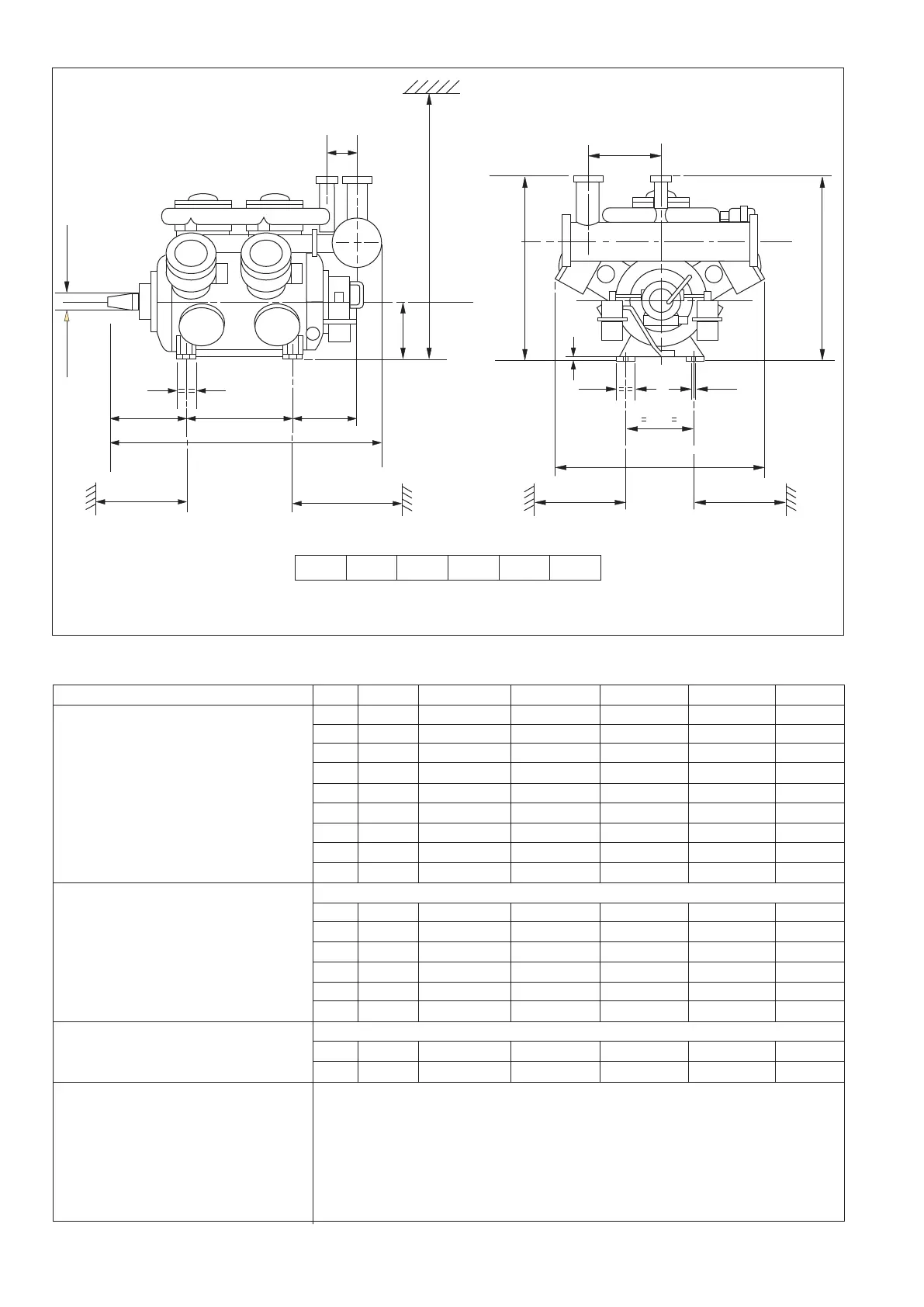
Overall Dimensions Of Single Stage Compressors
Compressor Type KC2 KC3 KC4 KC6 KC9 KC12
A 935 935 935 960 960 960
B 970 1130 970 1130 1130 1130
C 885 950 874 950 950 950
D 350 350 350 375 375 375
Main Dimensions E 397 150 193.5 150 150 150
F 391 391 402.5 402.5 426 426
G 215 215 380.0 570 960 1350
H 257 253 309 345 345 345
J 948 945 1150 1447 1861 2251
Minimum required free space for
removal of Flywheel U 905 905 920 915 940 940
Crankshaft (V or W) V 905 905 920 1015 1440 1875
W 670 670 860 1015 1440 1875
Pistons & cyl. liners X 1085 1160 1085 1160 1160 1160
Y 420 545 420 545 545 545
Gas suc. strainer element Z 900 900 900 1100 1100 1100
Main Connections hole diameter in (upper part of) counter flange
Suction 1 Ø77 Ø91 Ø91 Ø116 Ø143 Ø171
Discharge 2 Ø61 Ø61 Ø91 Ø91 Ø116 Ø116
Auxiliary Connections
Suction pressure 3
Discharge pressure 4 clamp coupling for Ø6x1 mm steel precision tube
Oil pressure 5
Oil charge & drain 6
Return from oil separator 7 1/2" BSP male
Oil leakage drain of Rotary shaft seal 8 clamp coupling for Ø6x1.0 mm steel precision tube
]
]
‘D’
‘A’
100
360
‘B’
‘Y’ ‘Z’
Ø 24
‘C’
‘U’
‘V’
‘F’ ‘G’
‘J’
‘W’
‘H’
Ø 85
120
310
‘X’
‘E’
20
KC 2
KC 3
KC 6 KC 9 KC 12KC 4
Figure No. 1
2
 Loading...