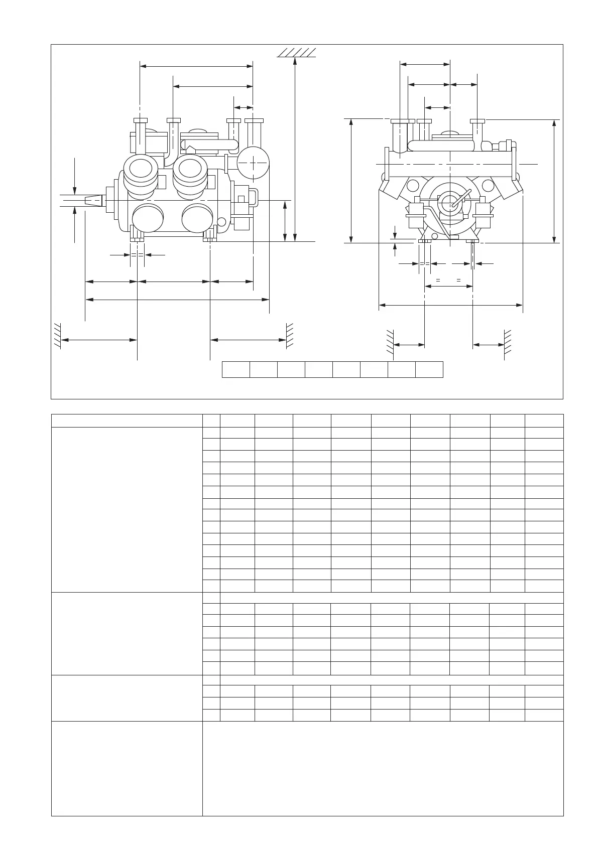
Overall Dimensions Of Two Stage Compressors
Compressor Type KC21 KC31 KC42 KC51 KC63 KC72 KC84 KC93 KC102
A 935 935 960 960 960 960 960 960 960
Main Dimensions B 1130 970 1130 1130 1130 1130 1130 1130 1130
C 843 874 950 950 950 950 950 950 950
Attention : D 270 0 270 0 0 0 0 0 0
KC21 & KC31 E 350 350 375 375 375 375 375 375 375
J is larger than F 280 173 270 310 270 270 270 270 270
H & for KC21 & G 192 223 185 195 191 191 191 191 191
KC42 K is equal to J H 285 565 960 885 1125 1125 1515 1515 1515
J 500 758 630 630 630 630 1020 1020 1020
K 500 160 630 150 150 150 150 150 150
L 385 402.5 402.5 402.5 426 426 426 426 426
M 215 380 570 570 960 960 1350 1350 1350
N 253 275 345 345 345 345 345 345 345
P 945 1150 1147 1147 1861 1861 2251 2251 2251
Minimum required free space for
removal of Flywheel U 905 920 915 915 940 940 940 940 940
Crank shaft (V or W) V 905 920 1015 1015 1440 1440 1875 1875 1875
W 670 860 1015 1015 1440 1440 1875 1875 1875
Piston & cyl. liner X 1160 1085 1160 1160 1160 1160 1160 1160 1160
Y 545 420 545 545 545 545 545 545 545
Gas suction strainer element Z 900 900 1100 1100 1100 1100 1100 1100 1100
Main Connections hole diameter in (upper part of) counter flange
LP Suction 1 Ø77 Ø91 Ø91 Ø116 Ø116 Ø143 Ø143 Ø143 Ø143
LP Discharge/HP Suction 2/3 Ø61 Ø61 Ø77 Ø61 Ø91 Ø77 Ø91 Ø91 Ø77
HP Discharge 4 Ø49 Ø49 Ø61 Ø61 Ø61 Ø61 Ø61 Ø61 Ø61
Auxiliary Connections
Suction pressure 5
Interstage pressure 6 clamp coupling for Ø6x1 mm steel precision tube
Discharge pressure 7
Oil pressure 8
Oil Charge & Drain 9 1/2" BSP male
Return from oil separator 10
Oil leakage drain of rotary shaft seal 11 Clamp coupling for Ø6x1 mm steel precision tube
Figure No. 2
‘H’
‘J’
85
310
‘K’
‘N’‘M’‘L’
‘P’
‘U’
‘V’
‘W’
‘X’
‘E’
‘F’ ‘D’
‘G’
‘A’
‘C’
100
Ø 24
360
‘B’
‘Y’ ‘Z’
120
Ø 85
20
KC 21
KC 31
KC 42 KC 51
KC 63
KC 72
KC 93
KC 102
]
]
3
 Loading...