5-8
Electrical Shock Hazard
Disconnect power before servicing.
Replace all parts and panels before operating.
Failure to do so can result in death or electrical shock.
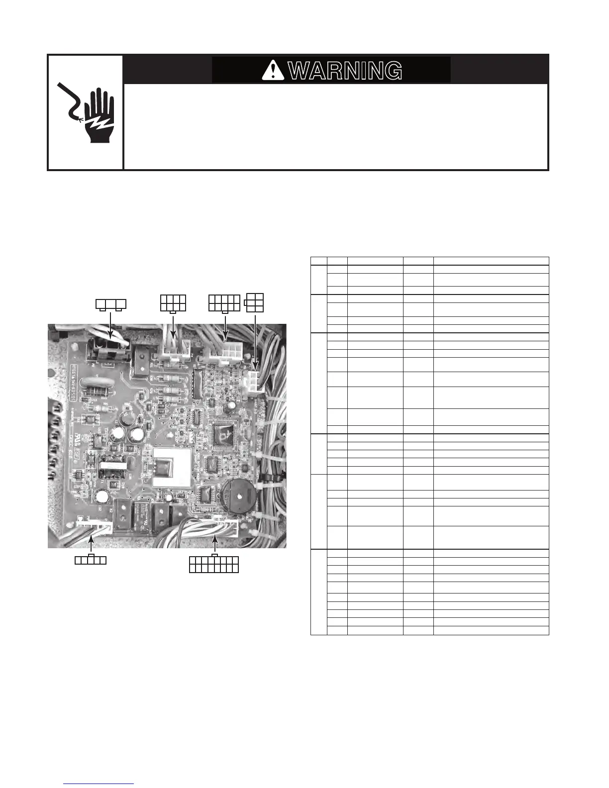
MAIN CONTROL BOARD
Refer to page 4-12 for the procedure for accessing the main control board.
NOTE: See the chart for the main control board test specifications.
PLUG PIN # DESCRIPTION OUTPUT CONDITION
P2
1 Communication Line N/A
2 Display V
oltage 12 VDC Measured at pins 2 & 3
3 GND GND
P3
1 Ref.
Thermistor GND
2 Frz.
Thermistor GND
3 Ref.
Thermistor Output 5 VDC Measured at pins 1 & 3
4 Frz.
Thermistor Output 5 VDC Measured at pins 2 & 4
P4
1 Ref. Door Sw Enable 120 V
AC
2 Frz. Door Sw Enable 120 V
AC
3 N/A
4 Ref. Door Input 120 V
AC Voltage present when door is open
5 Ice Maker V
alve Input 120 VAC Voltage present when ice maker is energized
6 Dispenser V
alve Input 120 VAC Voltage present when dispenser valve is energized
7 Bimetal Input 120 V
AC Voltage present when bimetal is closed
8 Frz. Door Input 120 V
AC
P5
1
AC GND AC GND
2
AC L1 120 VAC
3
AC Neutral AC Neutral
4
AC Neutral AC Neutral
5
AC L1 120 VAC
P6
1 Condenser Fan 120 V
AC Voltage present when condenser fan is on
2 N/A
3 N/A
4 Defrost Heater 120 V
AC Voltage present when defrost heater is on
5 Ice Maker Enable 120 V
AC
Voltage present when I/M bail arm is down & I/M
is active
P7
1
Air Door
2
Air Door
3 Compressor Drive 3 - 6 VDC Measured at pins 3 & 8
4 Evap. Fan Feedback N/A
5 Evap. Fan Constant 12 VDC Measured at pins 5 & 9
6
Air Door
7
Air Door
8 Compressor Drive 3 - 6 VDC Measured at pins 3 & 8
9 Evap. Fan Ground Evap. GND
10 Evap. Fan Run V
oltage 5 - 12 VDC Measured at pins 9 & 10