5-1
COMPONENT TESTING
Electrical Shock Hazard
Disconnect power before servicing.
Replace all parts and panels before operating.
Failure to do so can result in death or electrical shock.
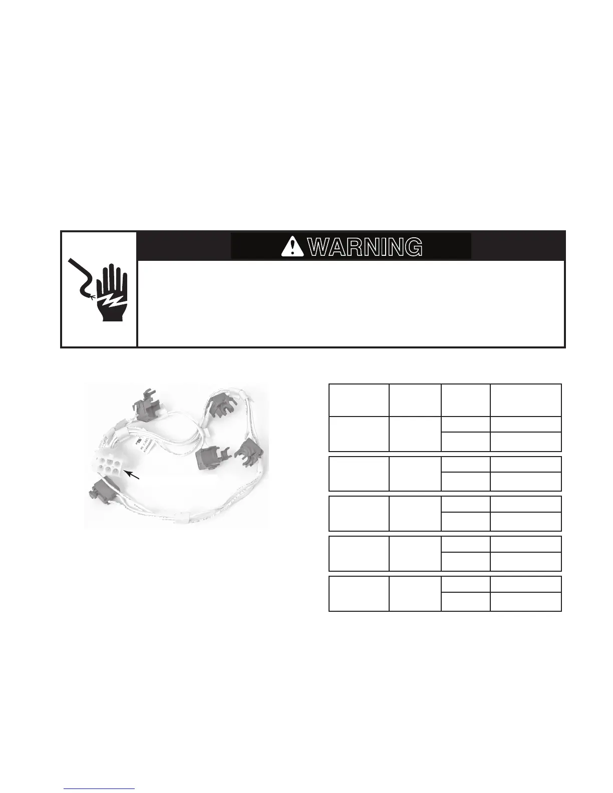
SPARK SWITCHES
Refer to page 4-3 for the procedure for access-
ing the spark switches.
1. Unplug cooktop or disconnect power.
2. Disconnect the spark switch 6-pin connec-
tor.
3. Set the ohmmeter to the R x 1 scale.
4. Rotate the valve to the setting shown in
the chart. Touch the ohmmeter test leads
to the indicated connector pins. The meter
should indicate an open or closed state.
Before testing any of the components, perform
the following checks:
The most common cause for control failure •
is corrosion on connectors. Therefore, dis-
connecting and reconnecting wires will be
necessary throughout test procedures.
All tests/checks should be made with a •
VOM or DVM having a sensitivity of 20,000
ohms-per-volt DC, or greater.
Check all connections before replacing •
components, looking for broken or loose
wires, failed terminals, or wires not pressed
into connectors far enough.
Resistance checks must be made with •
power cord unplugged from outlet, and
with wiring harness or connectors discon-
nected.
Test
Points
Switch
Location
Valve
Setting
Meter
Reading
Pins P2-1
& P2-7
LF
OFF
Open (∞)
LITE
Closed (0 Ω)
Pins P2-2
& P2-7
LR
OFF
Open (∞)
LITE
Closed (0 Ω)
Pins P2-3
& P2-7
C
OFF
Open (∞)
LITE
Closed (0 Ω)
Pins P2-5
& P2-7
RF
OFF
Open (∞)
LITE
Closed (0 Ω)
Pins P2-4
& P2-7
RR
OFF
Open (∞)
LITE
Closed (0 Ω)
6-Pin Connector