2-13
Style 2: The cap does not have a slot and
requires a wrench to be removed.
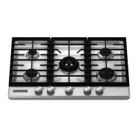
Remove the access cap by using a wrench,
turning the access cap counterclockwise.
Remove spring retainer from the cap by push-
ingagainsttheatsideofthespringretainer.
Look at the spring retainer to locate the “NAT”
or “LP” position. Turn over the spring retainer
so the “LP” is showing on the bottom. Snap the
spring retainer back into the cap. Reinstall the
cap onto the regulator.
A. Access cap
B. Gasket
C. Gas pressure regulator
D. LP position
E. NAT position
A
B
CDE
4. Test the gas pressure regulator and gas
supply line.
The regulator must be checked at a minimum
1" (2.5 cm) water column above the set pres-
sure. The inlet pressure to the regulator should
be as follows for operation and checking the
regulator setting:
LP Gas:
Minimum pressure 10" (25.4 cm) W.C.P.
Supply pressure 14" (35.5 cm) W.C.P.
Gas Supply Pressure Testing
Line pressure testing above ½ psi gauge
(14" WCP)
The cooktop and its individual shutoff valve
must be disconnected from the gas supply
piping system during any pressure testing of
that system at test pressures in excess of ½
psi (3.5 kPa).
Line pressure testing at ½ psi gauge (14"
WCP) or lower
The cooktop must be isolated from the gas
supply piping system by closing its individual
manual shutoff valve during any pressure testing
of the gas supply piping system at test pressures
equal to or less than ½ psi (3.5 kPa).
5. If installed, remove the burner grates.
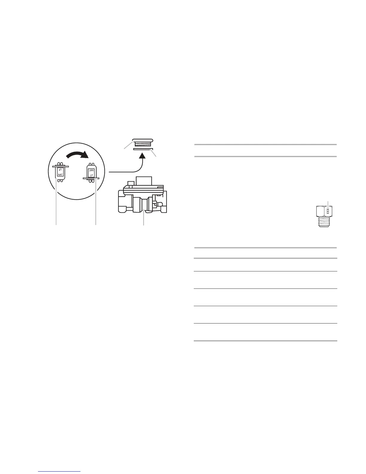
Use the following charts to match the correct
gasoricespudwiththeburnerlocationand
model being converted.
LP Gas Orice Spud Chart
Burner Models
Burner
Rating
ColorStamp
(A)
Size
5,000 BTUWhite
(no color)
066 0.66 mm
6,000 BTUGreen 074 0.74 mm
8,000 BTUYellow083 0.83 mm
9,100 BTUBlack 0890.89 mm
11,000 BTUOrange 097 0.97 mm
12,000 BTU
Outer
Inner
White
No color
099
6
0.99 mm
0.5*0.5 mm
14,000 BTU
Outer
Inner
Ye llow
No color
108
6
1.08 mm
0.5*0.5 mm
16,000 BTU
Outer
Inner
Orange
No color
115
6
1.15 mm
0.5*0.5 mm
A. Size
stamp
Model
No.
Right
front
Right
rear
Center
(outer)
Center
(inner)
Left
front
Left rear
KFGS306 089
Black
074
Green
099
White
6
No color
083
Ye llow
066
White
(no color)
KFGS366 089
Black
074
Green
108
Ye llow
6
No color
089
Black
066
White
(no color)
KFGU706 097
Orange
074
Green
099
White
6
No color
083
Ye llow
066
White
(no color)
KFGU766 089
Black
074
Green
115
Orange
6
No color
097
Orange
066
White
(no color)
A