56
Chapter 1 Handling the Product
1
AssemblingConnecting Cables
■
Manual Trolley Type
■
125 kg~5 t
■
Direct connection
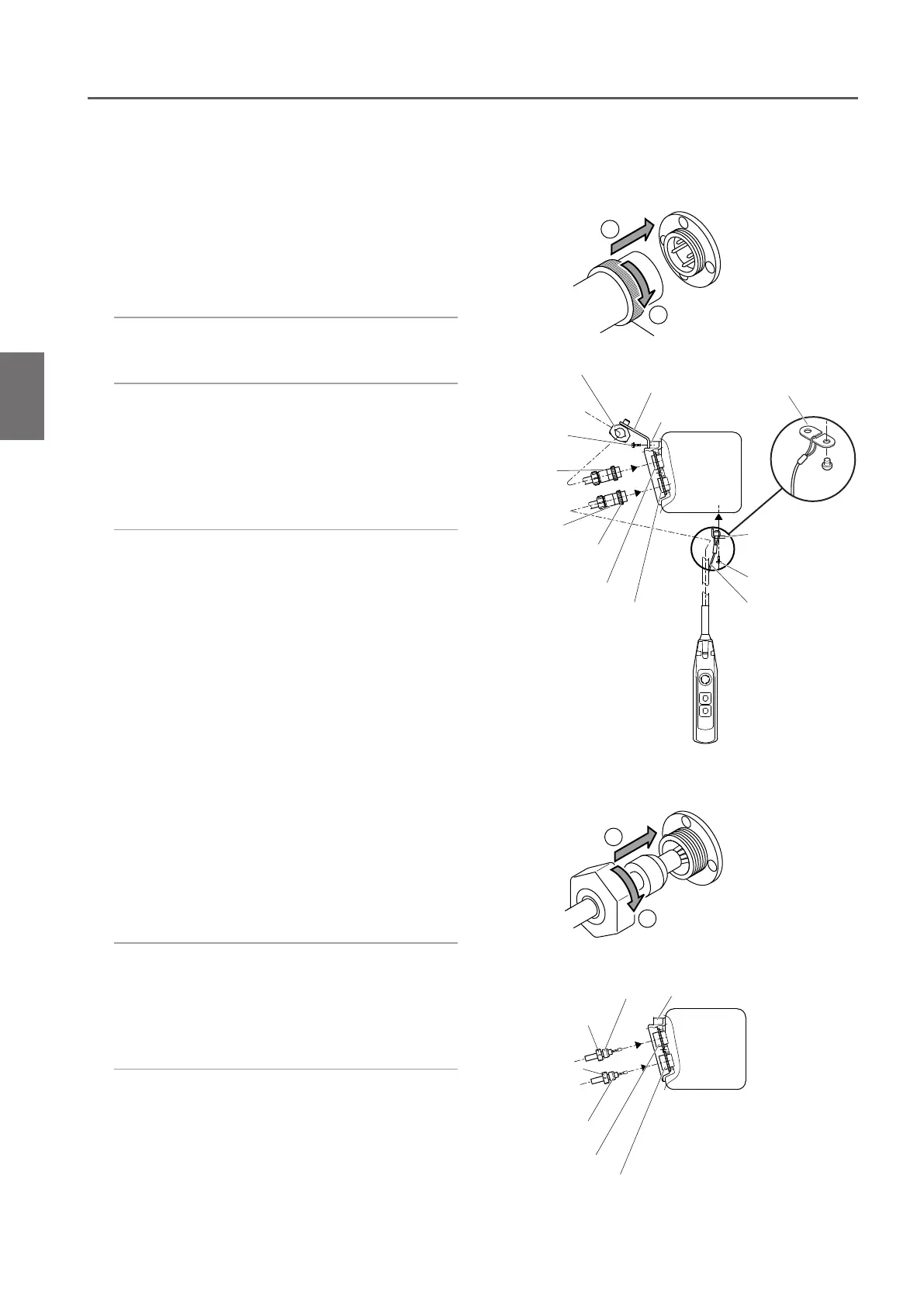
2) Fix the Power Cable using cable support
with a slack.
1) Insert the 4-pin plug of the Power Cable
to the socket (4P) and tighten the Lock
Ring securely.
●
Connecting the Power Cable
●
Connecting the Push Button Switch Cord
1) Insert the 8-pin connector plug of the
Push Button Cord to the connector
socket (8P) and tighten the Lock Ring
securely.
2) Pass the Cable Support L into the ring at
the end of the Protection Wire. Put the
Protection Wire in the notch of the Cable
Support L.
Then fix the Cable Support L to the body
size (at the bottom face of the Gear Case).
1
2
Cable Packing Connector Socket holder
Holder A
Holder A
Holder C (upper side)
Holder C (lower side)
1
2
Cable holder
Cable holder arm
Socket frame
Connector
Plug (8P)
Connector
Socket (8P)
Cable Support L
Pan head screw
Protection wire
Lock Ring
Connector
Plug (4P)
Pan head
screw
Connector
Socket (4P)
Cable Support L
2) Connecting the Push Button Cord
Insert the Push Button Cord into the
Holder C (lower side) of the Connector
Socket holder. Turn the Holder A to
connect the cord securely.
3) Carry out wiring correctly in accordance
with the wiring diagram inside the
Controller Cover.
1) Connecting the Power Cable
Insert the Power Cable into the Holder
C (upper side) of the Connector Socket
holder. Turn the Holder A to connect the
cable securely.
Assembling (continued)
* Items other than above are the same to those
described for Plug Connection.