Service ManualService Manual
Operating Lights marLEDOperating Lights marLED
®®
E9 / E9i / E9 / E9i / E15E15
16 16 V V 1.01.0
4.3.24.3.2
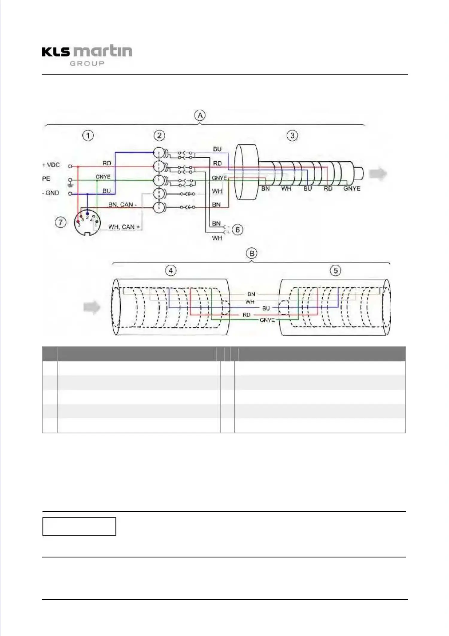
Circuit Diagram for 5-Pole Tracking Arm with Wall-Mounted Control PanelCircuit Diagram for 5-Pole Tracking Arm with Wall-Mounted Control Panel
and backLite Optionand backLite Option
A
A TrTracackiking ng ararm m BB SpSpriring ng ararmm
1 1 Plug Plug for for connection connection to to ceiling ceiling tube tube 4 4 Socket, Socket, tracking tracking arm arm sideside
2 2 Slip Slip ring ring 5 5 Socket, Socket, light light head head sideside
3 Plug3 Plug
6 6 backLite backLite connection connection optionoption
7 7 Socket, Socket, 5-pole 5-pole (DIN (DIN 41524, 41524, soldering soldering side)side)
Ceiling tube < 400 mm -> DIN socket (7) soldered directly to cableCeiling tube < 400 mm -> DIN socket (7) soldered directly to cable
Ceiling tube > 400 mm -> DIN socket (7) soldered directly to cable, plus 5-pole extensionCeiling tube > 400 mm -> DIN socket (7) soldered directly to cable, plus 5-pole extension
cable (plug / socket)cable (plug / socket)
In multi-light setups, all CAN connecting cables (CAN+ WH, CAN- BN) are parallel-soldered toIn multi-light setups, all CAN connecting cables (CAN+ WH, CAN- BN) are parallel-soldered to
DIN socket (7).DIN socket (7).
When using a combination of lights, please note the different color marks on the connectors.When using a combination of lights, please note the different color marks on the connectors.
Tracking arm 1:Tracking arm 1:
rered d TrTracackiking ng ararm m 3:3: blblueue
Tracking arm 2:Tracking arm 2: yelyellow low TraTrackicking ng arm arm 4:4: gregreenen
NOTICENOTICE