Service ManualService Manual
Operating Lights marLEDOperating Lights marLED
®®
E9 / E9i / E9 / E9i / E15E15
28 28 V V 1.01.0
4.6.44.6.4
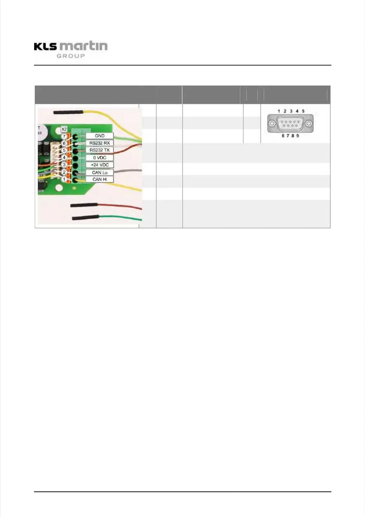
Pin Configuration X2 (CAN, RS232)Pin Configuration X2 (CAN, RS232)
Illustration
Illustration X2 X2 Pin Pin ColorColor
Signal Signal / / ConnectConnect
ionion
Pin Pin RS232 RS232 PlugPlug
77
GN GN RS RS 232 232 GND GND 55
66
WH WH RS RS 232 232 RX RX 22
55
BN BN RS RS 232 232 TX TX 33
--
YEYE
The yellow wire of the RS232 cable is notThe yellow wire of the RS232 cable is not
used.used.
44
BN BN Supply Supply GNDGND
33
GN GN Supply Supply +24 +24 VV
22
GY GY CAN CAN LoLo
11
YE YE CAN CAN HiHi
The JST connector and the terminal block of X2 are wired on the board in parallel (indicated byThe JST connector and the terminal block of X2 are wired on the board in parallel (indicated by
white lines in the illustration above). The pins 4 and 5 of the JST connector are guided inwhite lines in the illustration above). The pins 4 and 5 of the JST connector are guided in
parallel to pin 4 of the terminal block. If the plug must be cut from the cable, the cables areparallel to pin 4 of the terminal block. If the plug must be cut from the cable, the cables are
connected in the terminal block.connected in the terminal block.
T T Tx Tx BN 3BN 3
G G GND GND GN GN 55