Service ManualService Manual
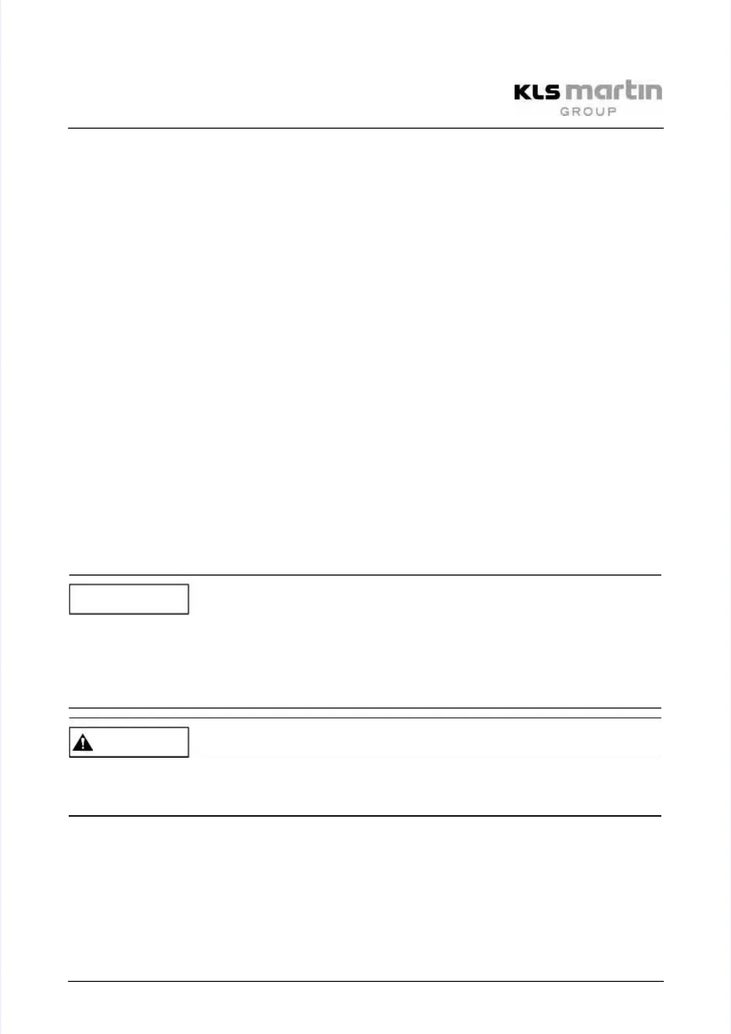
Operating Lights marLEDOperating Lights marLED
®®
E9 / E9i / E15E9 / E9i / E15
V V 1.0 1.0 2525
For installation of the power supply on a mounting rail, the support plate is replaced by theFor installation of the power supply on a mounting rail, the support plate is replaced by the
mounting rail adapter (4) of the accessory / grounding kit. The mounting rail adapter ismounting rail adapter (4) of the accessory / grounding kit. The mounting rail adapter is
screwed to the bottom of the SMPS with two of the three countersunk screws M4 x 8mm DINscrewed to the bottom of the SMPS with two of the three countersunk screws M4 x 8mm DIN
7991 (5) which were used earlier to screw the support plate to the SMPS (see location (3) in7991 (5) which were used earlier to screw the support plate to the SMPS (see location (3) in
Fig. 4-1).Fig. 4-1).
4.64.6 Cable Connection CAN and RS232Cable Connection CAN and RS232
4.6.14.6.1
CAN Bus and AddressesCAN Bus and Addresses
The CAN bus signal requires 3 leads: CAN+, CAN- and reference level. It interconnectsThe CAN bus signal requires 3 leads: CAN+, CAN- and reference level. It interconnects
processor-controlled circuit boards featuring a CAN bus connector.processor-controlled circuit boards featuring a CAN bus connector.
Each of the processors connected can, in principle, give commands to one of the others andEach of the processors connected can, in principle, give commands to one of the others and
execute their commands. The address that is set on the DIP switch SW6 within the lamp bodyexecute their commands. The address that is set on the DIP switch SW6 within the lamp body
corresponds to the number by which the light can be controlled on the wall box.corresponds to the number by which the light can be controlled on the wall box.
A camera-ready light has the address 0 in a light combination. The remaining lights getA camera-ready light has the address 0 in a light combination. The remaining lights get
sequential numbers (1, 2, 3).sequential numbers (1, 2, 3).
4.6.24.6.2
CAN Bus Terminating Resistor RCAN Bus Terminating Resistor R
AA
The CAN bus must be fitted with a terminating resistor at both ends. In KLS Martin lights, eachThe CAN bus must be fitted with a terminating resistor at both ends. In KLS Martin lights, each
printed board with CAN bus features a terminating resistor that can be enabled or disabled andprinted board with CAN bus features a terminating resistor that can be enabled or disabled and
is switched on for all devices whose address is “0” (i.e. remains disabled for all other boards).is switched on for all devices whose address is “0” (i.e. remains disabled for all other boards).
Even if one single light is operated individually, its terminating resistor must be set, as anyEven if one single light is operated individually, its terminating resistor must be set, as any
combined electronics use an internal CAN-Bus and rely on the correct functioning of thecombined electronics use an internal CAN-Bus and rely on the correct functioning of the
communication. Internal resistance in the CAN-Bus must be 40communication. Internal resistance in the CAN-Bus must be 40
ΩΩ
–120–120
ΩΩ
••
Measure in current-free state.Measure in current-free state.
Possible malfunctions in case of incorrect setting of the Possible malfunctions in case of incorrect setting of the terminating resistor!terminating resistor!
If too many or too few terminating resistors are set, unforeseen malfunction can occur.If too many or too few terminating resistors are set, unforeseen malfunction can occur.
Every wall box is delivered with a RS232 cable that can be used for serial activation of theEvery wall box is delivered with a RS232 cable that can be used for serial activation of the
lights.lights.
The wall box can control multiple lights. A connection cable (15 m) is led from each ceilingThe wall box can control multiple lights. A connection cable (15 m) is led from each ceiling
tube (1) to the wall box (3).tube (1) to the wall box (3).
NOTICENOTICE
CAUTIONCAUTION