Service ManualService Manual
Operating Lights marLEDOperating Lights marLED
®®
E9 / E9i / E9 / E9i / E15E15
24 24 V V 1.01.0
4.5.64.5.6
Installation on a support plateInstallation on a support plate
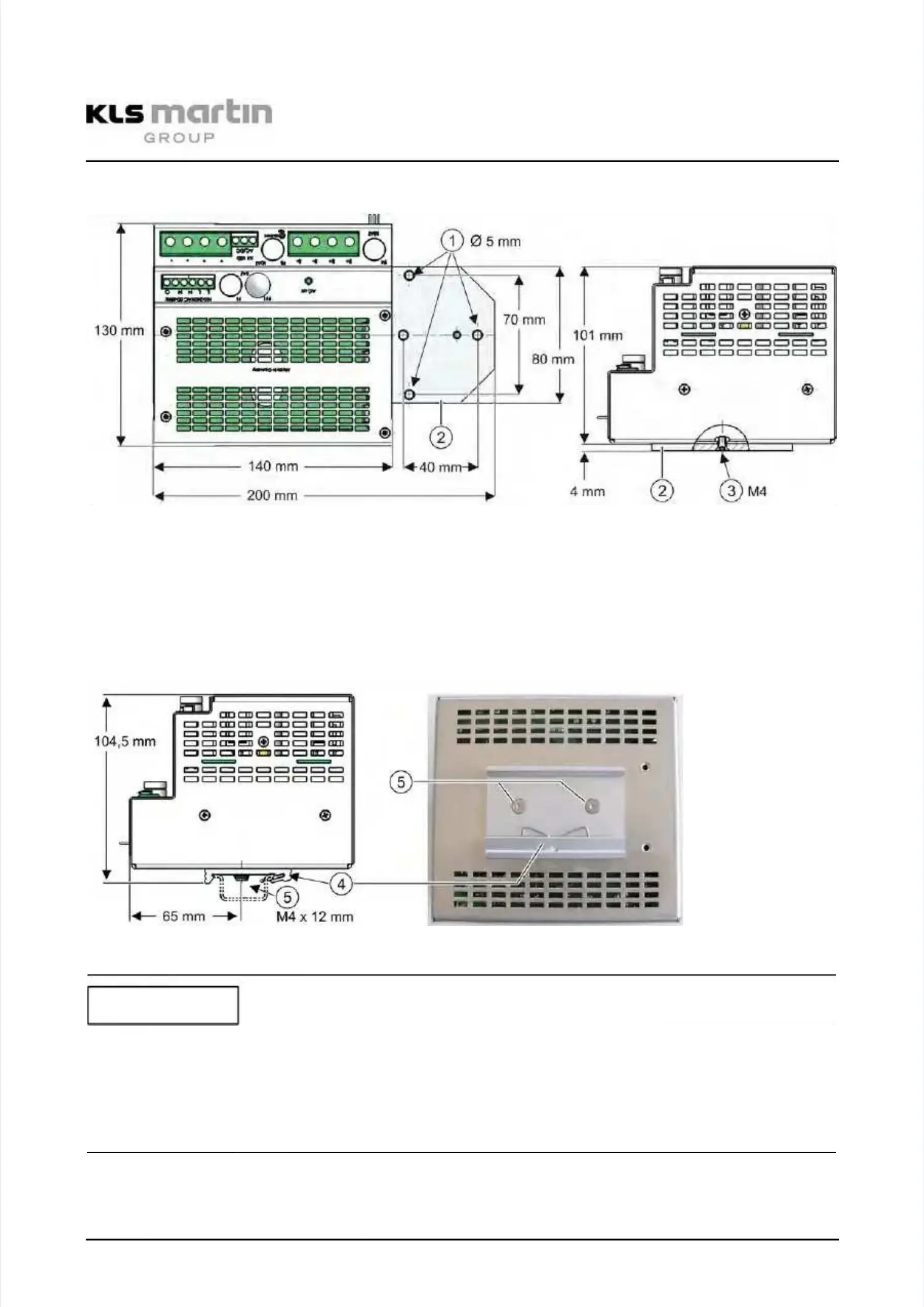
Fig. Fig. 4-1: 4-1: Mounting Mounting dimensions dimensions power power module module without without mounting mounting plateplate
The power module is mounted to the ceiling tube with three screws (1) and theThe power module is mounted to the ceiling tube with three screws (1) and the
support plate (2), where it is screwed on with countersunk screws M4x 8mm DIN 7991 (3).support plate (2), where it is screwed on with countersunk screws M4x 8mm DIN 7991 (3).
4.5.74.5.7
Mounting rail installationMounting rail installation
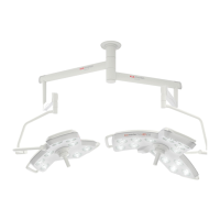
Fig. Fig. 4-2: 4-2: Mounting Mounting dimensions dimensions power power module module on on optional optional mounting mounting rail rail adapter adapter (4)(4)
Possible damage to the power module by excessive screwing!Possible damage to the power module by excessive screwing!
If too long screws are used to screw the support plate or the mounting rail adapter to theIf too long screws are used to screw the support plate or the mounting rail adapter to the
power module, the electronics of the module can be damaged!power module, the electronics of the module can be damaged!
Maximum length of engagement into the power module is 6mm!Maximum length of engagement into the power module is 6mm!
NOTICENOTICE