58
Tillage Tool Adjustment
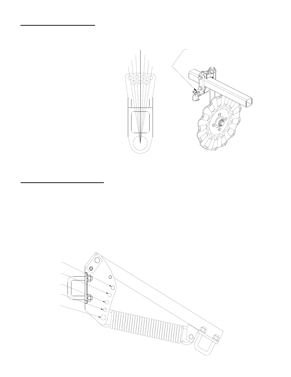
The operating angle of the secondary
tillage tool is determined by the location of
the 3/8” adjustment pin. The figure to the
right shows the available running angles
from 0° to 9° to the left and to the right. To
adjust the operating angle, remove the
adjustment pin, turn the tillage shaft until
the hole in lower flag aligns with the
desired adjustment hole, and reinsert the
adjustment pin. It should be noted that the
tillage stem is held in place by a 1-1/4
Nylon Locknut. If this locknut needs
adjusting, be sure that it is tight enough to
hold the tillage stem stable but not so tight
that it will not allow the stem to rotate. Soil
conditions will normally dictate the angle
of the disc or wheels. Soft or conventional
soils will generally require less angle than
strip or no-till soils.
9°
6°
3°
0°
3°
6°
9°
ADJUSTMENT PIN
Finishing Tool Adjustment
30 LB
50 LB
80 LB
115 LB
150 LB
KMC offers a choice of finishing tools that include either a rubber tire roller or a crumbler basket. Both
types of finishing tools are attached to the toolbar using a spring loaded reach arm that provides down
pressure. To adjust the down pressure on the finishing tool, raise the main toolbar until all spring
tension in the down pressure spring is released and the finishing tool is off the ground. Remove the
adjustment pin from the front mount bracket while supporting the down pressure spring. Raise or lower
the spring until the spring hook is aligned with the desired adjustment hole and reinsert the adjustment
pin. The figure below shows the adjustment holes in the front mount bracket and their corresponding
down pressure forces.
 Loading...