TP-6694 7/18 15Section 1 Specifications and Features
Section 1 Specifications and Features
1.1 Introduction
The spec sheets for each generator set provide model-
specific generator and engine information. The
controller spec sheet provides specifications for this
controller. Refer to the respective spec sheet for data
not supplied in this manual. Refer to the generator set
service manual, installation manual, engine operation
manual, and engine service manual for additional
specifications.
1.2 Controller Features
The controller features include the annunciator lamp,
digital display and pushbutton/rotary selector dial,
switches and controls, and fuses and terminal strip. The
following paragraphs detail the features by general
topics.
See Figure 1-1 for an illustration of the controller front
panel.
The controller features, accessories, and menu displays
depend upon the engine electronic control module
(ECM) setup and features. Controller features apply to
generator set models with ECM and non-ECM engines
unless otherwise noted.
Note: Press the pushbutton/rotary selector dial to turn
on the controller lights and display. The lights and
display turn off 60 minutes after the last entry
when in the AUTO mode.
Note: After about 5 minutes of no user input
(pushbutton/rotary selector dial or buttons), the
menu is reset to the top of the main menus and
auto-paging activates for the Overview
submenus.
Note: Measurements display in metric or English units.
Use the Generator Set System menu to change
the measurement display.
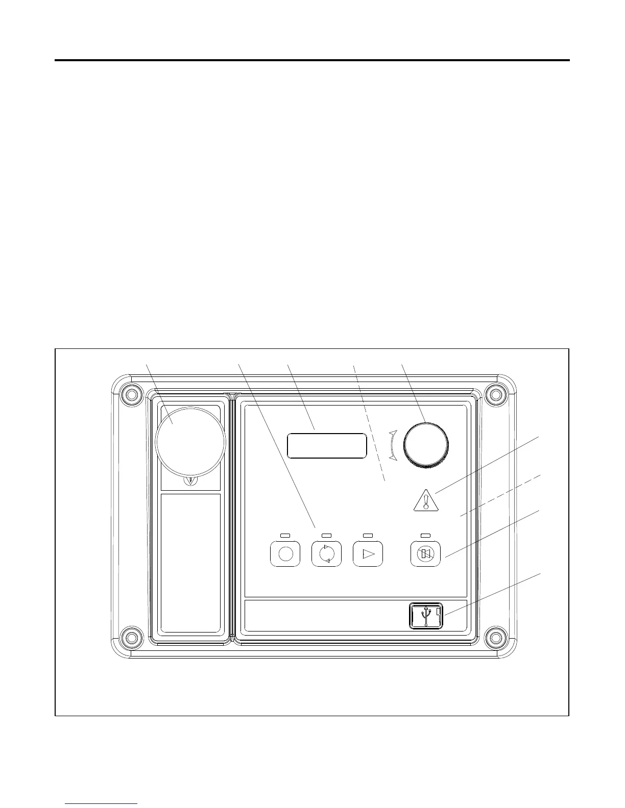
1. Emergency stop switch
2. Generator set master control switches,
OFF/RESET--AUTO--RUN buttons with lamps
3. Digital display
4. Alarm horn (behind panel)
5. Pushbutton/rotary selector dial
6. Annunciator fault lamp
7. Controller terminal strips (on circuit board)
8. Alarm silence/lamp test button with lamp
9. Mini USB connection
GM65741-
12 45
7
8
3
6
FAULT
OFF/RESET AUTO RUN ALARM SILENCE/
LAMP TEST
9
Figure 1-1 Controller with Digital Display and Pushbutton/Rotary Selector Dial
 Loading...

