TP-6694 7/1826 Section 1 Specifications and Features
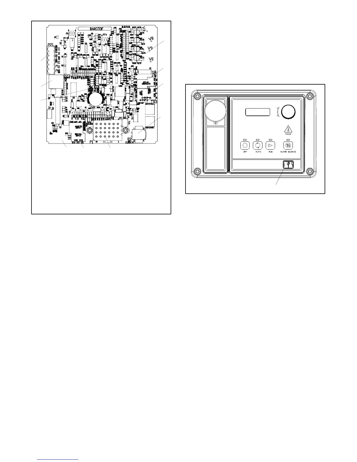
1. (4) push-on terminal connectors
2. TB2 4-position terminal block
3. TB3 6-position terminal block
4. P2 6-pin connector
5. P1 24-pin connector
6. TB1 6-position terminal block
7. P22 3-pin connector
8. P30 jumper (Wound Field or Fast Response)
9. P23 8-pin connector (RJ45)
10. P21 6-pin connector (for RS-485 communication)
GM64345-1-A
1
2
3
4
5
6
10
7
9
8
Figure 1-5 Main Circuit Board Connectors
P21 (6-Pin) Connector for (RS-485) connection of
optional RSA or Modbusr communication.
P22 (3-Pin) Connector for engine ECM. Alternate CAN
connection.
P23 (8-Pin) Connector (RJ45) for optional input/output
(I/O) module circuit board.
Refer to Section 6.2, Accessory Connections for
specific connections of the following terminal block
connections.
TB1 (6-Position) Terminal Block for analog and digital
inputs.
TB2 (4-Position) Terminal Block for K1 relay outputs.
TB3 (6-Position) Terminal Block for E-stop, remote
start contacts, and aux. input connections.
1.2.7 Terminal Jumper
A circuit board P30 jumper is set based on alternator
type—Wound Field (300 kW and larger) or
Fast Response (less than 350 kW). The jumper is
factory set and needs no further adjustment. See
Figure 1-5 for location of the P30 jumper.
1.2.8 Communication Ports
The main logic circuit board contains a single mini USB
communication port for PC connections, see Figure 1-6.
For Modbusr communication using RS-485, see
Figure 1-5 (P21). Refer to the List of Related Materials
in the Introduction for corresponding SiteTe cht
software and/or communication installation information.
1. Mini USB connection
GM65741-
1
Figure 1-6 Communication Port
1.2.9 Fuses
AC Circuit Fuses (TB5). Fuses are located inside the
generator set control box. See Figure 1-7
D 1.5-Amp (V7) fuse protects L1 sensing input to
interconnection circuit board.
D 1.5-Amp (V8) fuse protects L2 sensing input to
interconnection circuit board.
D 1.5-Amp (V9) fuse protects L3 sensing input to
interconnection circuit board.
DC Circuit Fuses are located on the controller circuit
board. See Figure 1-8.
D 1-Amp (F1) auto-resettable, fuse protects the
controller circuits.
D 1-Amp (F2) auto-resettable fuse protects the
controller circuits.
D 12-Amp (F3) non-replaceable fuse protects the
engine/starting circuitry and accessories.
Modbusr is a registered trademark of Schneider Electric.
 Loading...

