TP-6694 7/1868 Section 3 Scheduled Maintenance
To change the fuel type, change the electrical
connections to the engine ECM. The engine ECM has
fuel tables and spark advance curves programmed for
both natural gas and LPG. The information following, in
Figure 3-3, and in Figure 3-5 generally apply to all
models and all fuels. Be sure to review the respective
wiring diagram for your specific model for possible
special applications.
Natural Gas Operation
D Disconnect lead 65 from lead N5.
D Disconnect lead 73B from the fuel valve.
D Connect lead 73A to the fuel valve.
LPG Vapor Operation
D Disconnect lead 73A from the fuel valve.
D Connect lead 73B to the fuel valve (LPG vapor).
D Connect lead 65 to lead N5 (ground).
LPG Liquid Withdrawal Operation
D Disconnect lead 73A from the fuel valve.
D Connect lead 73B to the fuel valve (LPG liquid
withdrawal).
D Connect lead 65 to lead N5 (ground).
Auto Changeover Natural Gas/LPG Vapor
Operation
D Disconnect lead 65 from N5.
D Connect lead N5 to LFP2 relay common terminal.
D Connect lead 73A to the fuel valve (natural gas).
D Connect lead 73B to the fuel valve (LPG vapor).
Eng.
ECM
Natural
Gas
LPG
Vapor
LPG
Liquid
Auto
Changeover
73A
QCON --7
(NG fuel
valve)
not used
QCON --7
(NG fuel valve)
N5 not used 65 65 LFP2--COM
73B not used QCON--10 (LPG fuel valve)
65 not used N5 N5 not used
63 LFP1--NC low fuel pressure sensor (if used)
70E2 P6--B (15 amp fuse)
Figure 3-3 Gaseous Fuel Electrical Connections
3.6.4 Fuel System Changeover Kits
(Dual Fuel)
Automatic Changeover
A changeover fuel system kit provides automatic
changeover from natural gas to LPG vapor. The
primary and backup fuels each have a fuel valve. The
primary fuel is natural gas; the backup fuel is LPG
vapor. Before starting, both fuel valves are closed.
When the generator set starts, the primary fuel valve
opens. The primary fuel line has a pressure switch in
series with a relay connected to the start/run circuit.
When the primary fuel pressure drops below 0.6 kPa
(1.4 oz./in.
2
) or 6.4 cm (2.5 in.) water column , a relay
opens the backup fuel valve and closes the primary fuel
valve. When the primary fuel pressure rises above 0.6
kPa (1.4 oz./in.
2
) or 6.4 cm (2.5 in.) water column, the
generator set uses the primary fuel. Contact an
authorized service distributor/dealer for kit availability.
Emissions certified models use a single electronic-
controlled pressure regulator (EPR) for both fuels. A tee
fitting connects both fuels together upstream of the
EPR. During operation when using the secondary fuel, it
is normal for a small amount of secondary fuel to seep
back through the primary fuel valve. To counter this
situation, one of two methods is used depending upon
the generator set model: (1) a second valve (identical to
the primary fuel valve) is installed in a reverse
configuration on the primary fuel side or (2) a small vent
line is installed between the primary fuel inlet and the air
intake through a solenoid valve.
3.7 Crankcase Ventilation (CCV)
Heater Kit GM78171-KP1
Applies to 125/150 kW, 8.1 L GM- and 8.8 L PSI-
powered generator set models. Consult your local
generator set distributor/dealer for additional
information.
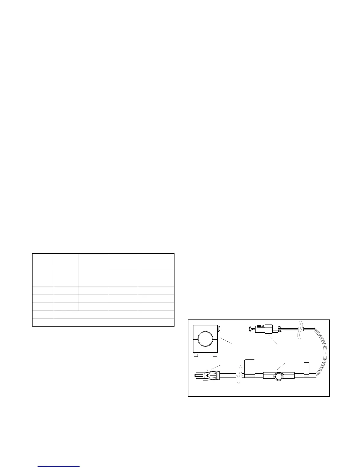
The crankcase ventilation (CCV) heater kit provides a
controlled heating source to the crankcase ventilation
system preventing freezing water buildup during cold
weather. The thermostat turns on at 4_C(40_F) and
turns off at 16_C(60_F) reducing energy consumption.
SeeFigure3-4.
1. Heater element
2. Inline connector
TT-1560
1
2
3
4
3. Thermostat
4. AC power cord
Figure 3-4 Crankcase Ventilation Heater Kit
 Loading...

