TP-6694 7/18 89Section 6 Accessories
Section 6 Accessories
6.1 Accessories and Connections
Several accessories help finalize installation, add
convenience to operation and service, and establish
state and local code compliance.
Accessories vary with each generator set model and
controller. Select factory-installed and/or shipped-
loose accessories. See Figure 6-1 for a list of available
kits. Obtain the most cur rent accessory information
from your local authorized service distributor/dealer.
This section illustrates several accessories available at
print time of this publication. Accessory kits generally
include installation instructions. See wiring diagrams
manual for electrical connections not shown in this
section. See the installation instructions and drawings
supplied with kit for information on kit mounting location.
The instructions provided with the accessory kit
supersede these instructions where there are
differences. In general, run AC and DC wiring in
separate conduit. Use shielded cable for all analog
inputs. Observe all applicable national, state, and local
electrical codes during accessory installation.
See Section 6.2, Accessory Connections, for terminal
identification.
Kit Description
Battery Charger (with alarms)
Common Fault/Failure (32A) Connections
Fifteen-Relay Dry Contact Board with NO and NC Contacts
Gas Fuel Valve
Input/Output Module Board
Key Switch
Low Fuel (Level) Switch
Low Fuel (Pressure) Switch
Manual Speed Adjust
Prime Power Switch
Remote Emergency Stop
Remote Reset Feature
Remote Serial Annunciator
Run Relay
Shunt-Trip Line Circuit Breaker
Figure 6-1 Optional Accessories
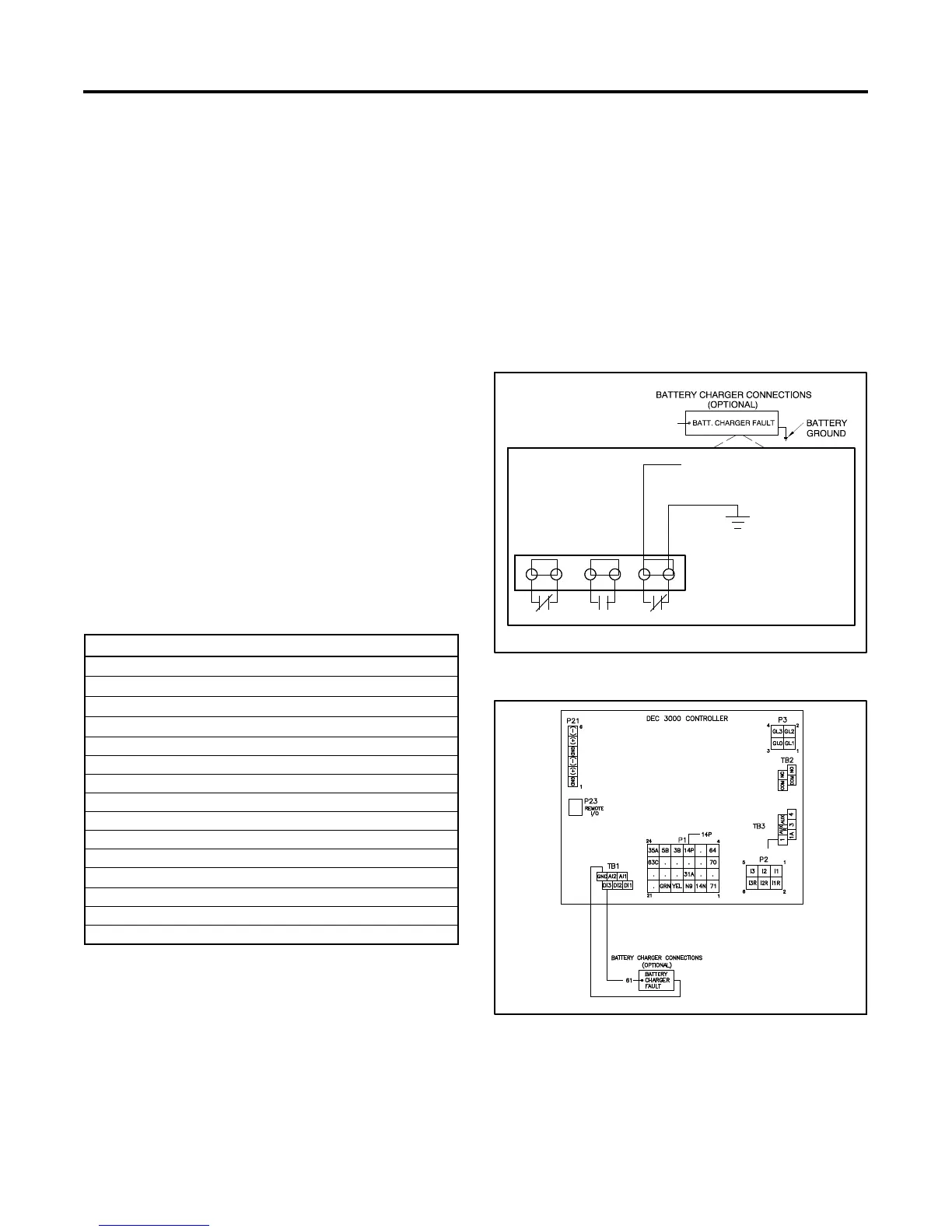
6.1.1 Battery Charger Kit with Alarm
Option
The battery charger with alarm option provides battery
charging to the engine starting battery(ies) and
connects to the controller for fault detection. Battery
chargers for 12- or 24-volt models are available as a
generator set accessory. See Figure 6-2 and Figure 6-3
for battery connections.
Note: On charger GM87448, the Battery Charger Fault
is communicated through CAN communication
and the connection on TB1 is not used.
GM16088A-A/TP--6694
BATTERY CHARGER
ALARM TERMINAL
STRIP
CHARGER
MALFUNCTION
LV HV CM
CONNECT TO TB1
Figure 6-2 Battery Charger Connections
GM67191-B
Figure 6-3 Battery Charger to Controller Connection
 Loading...

