TP-6694 7/1884 Section 5 Voltage Reconnection
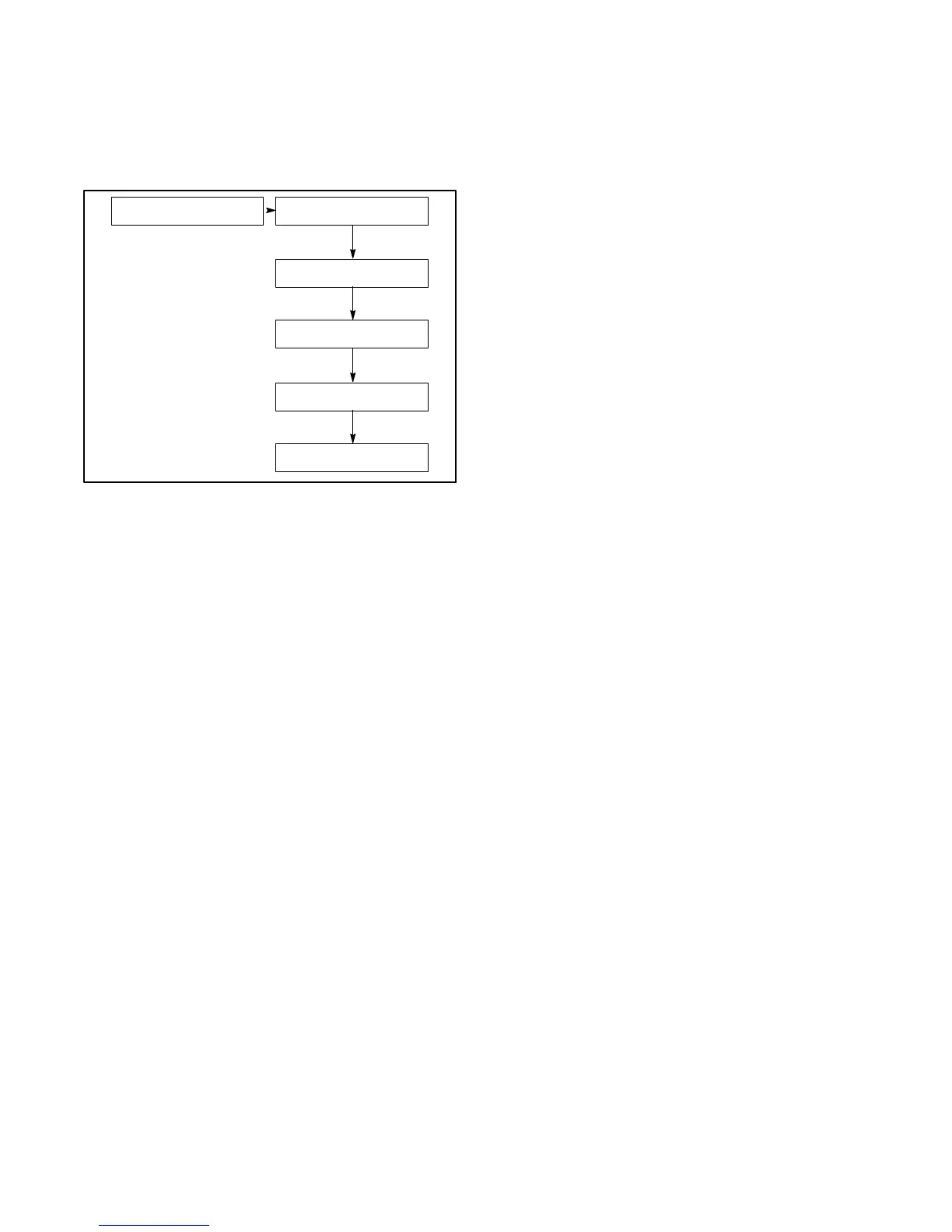
2. Turn the controller pushbutton/rotary selector dial
until it stops at the Volt Select menu. See
Figure 5-1.
Note: If the Volt Select menu does not appear, the
controller voltage selection feature was not
activated using SiteTecht software.
Volt Select: ---->
###/### V # Ph
139/240 V 3 Ph
120/240 V 1 Ph
120/208 V 3 Ph
120/240 V 3 Ph
277/480 V 3 Ph
TP-6694-2
Figure 5-1 Volt Select Menu
3. Press the selector dial and the voltage selection
option (second line on the display) will start to flash.
4. Turn the selector dial clockwise or
counterclockwise until the desired voltage
selection option appears.
5. Press the selector dial. The second line on the
display will stop flashing and the new voltage will
appear.
6. Rotate the generator set voltage selector switch (if
equipped) to match the desired voltage shown on
the controller display. Skip steps 7--9 and go to
step 10.
If the generator set does not have a voltage
selection switch, continue to step 7
7. Disconnect the generator set engine starting
battery, negative (--) lead first. Disconnect power to
the battery charger (if equipped).
8. Use Figure 5-2, Figure 5-3, or Figure 5-5 to
determine the generator set voltage configuration.
Note the original voltage and reconnect as needed.
Route leads through current transformers (CTs)
and connect them according to the diagram for the
desired phase and voltage.
Note: Position current transformers CT1, CT2,
and CT3 with the dot or HI side CT marking
toward the generator set.
9. Reconnect the battery, negative lead last.
10. Press the generator set master control RUN button
to start the generator set. Check the digital display
for correct voltages using 2.7.4 Generator
Metering.
11. Press the generator set master control
OFF/RESET button to stop the generator set after
completing the voltage adjustments.
5.3 Voltage Reconnection
Procedure
Note: This procedure applies to Decision-Makerr 3000
Controllers with software versions before 2.8
only.
1. Press the generator set master control
OFF/RESET button.
2. Disconnect the generator set engine starting
battery, negative (--) lead first. Disconnect power to
the battery charger (if equipped).
3. Use Figure 5-2, Figure 5-3, Figure 5-4, or
Figure 5-5 to determine the generator set voltage
configuration. Note the original voltage and
reconnect as needed. Route leads through current
transformers (CTs) and connect them according to
the diagram for the desired phase and voltage.
Note: Position current transformers CT1, CT2,
and CT3 with the dot or HI side CT marking
toward the generator set.
4. Reconnect the battery, negative lead last.
5. Use SiteTecht software to update the information.
6. Refer to 2.7.8 for generator set calibration at the
controller.
7. Press the generator set master control RUN button
to start the generator set. Check the digital display
for correct voltages using 2.7.4 Generator
Metering.
8. Press the generator set master control
OFF/RESET button to stop the generator set after
completing the voltage adjustments.
 Loading...

