TP-6461 1/08
103
Section 7 Component Replacement, Model KSP
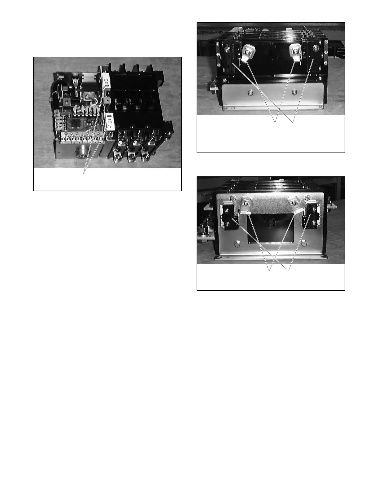
2. Replace the ON/OFF indicators and the cover.
Note: The ON/OFF indicators are not identical.
Locate them as shown in Figure 7-8.
1
6226
1. ON/OFF indicators
Figure 7-8 Assembled Units
3. Reinstall the auxiliary switch levers, if removed,
aligning the square indentation with the end of the
square shaft. See Figure 7-9 and Figure 7-10.
4. Reinstall the auxiliary switches, if removed. The
100 and 200 amp models use one bolt and one
alignment pin per switch. See Figure 7-9. Larger
models use two bolts per switch. See Figure 7-10.
1
6226
1. Auxiliary switch levers
2. Auxiliary switches
2
Figure 7-9 100 and 200 Amp Models
6226
1. Auxiliary switch levers
2. Auxiliary switches
1
2
Figure 7-10 400 Amp Models

 Loading...


